WHAT IT IS
RSBN (РСБН, from Радиотехническая система ближней навигации, "radio-technical short-range navigation system") is the Soviet and Russian system that tells a military aircraft where it is relative to an airfield beacon: which direction (azimuth) and how far (slant range). It also guides the aircraft down to the runway when it is paired with a separate landing beacon group called PRMG (ПРМГ, Посадочная радиомаячная группа). It works in the decimetre-wave UHF band, roughly 770 to 1000 MHz, so it is line-of-sight only, and it is built almost entirely out of timed pulses rather than the tones and phases that its Western cousins VOR and TACAN use. [DOCUMENTED]
The RSBN-4N (РСБН-4Н) is the ground half: the "beacon" (радиомаяк). It is the trailer with the big egg-shaped dome that sits beside many Russian, Soviet-era and former-Warsaw-Pact airfields. Inside the dome a directional antenna spins at 100 revolutions per minute. The airborne half is a separate box set in the aircraft (RSBN-2S "Свод", RSBN-6S "Ромб", A-312, A-324 and others). The two together are "the system"; neither means anything alone. [DOCUMENTED]
A pilot flying with it can do four jobs. (1) Read azimuth and range to the beacon continuously, so the aircraft's position is known to a few hundred metres without any satellite. (2) Fly to a point, along a straight track or around a circle (an "orbit") centred on the beacon, by steering a needle to zero. (3) Do a letdown, a controlled descent toward the airfield through cloud. (4) Land, in the "landing" mode, by switching the receiver to the PRMG beacons beside the runway, which produce a course needle and a glide needle like a Western ILS. A fifth job belongs to the ground: the same beacon lets the airfield controller see the aircraft on a remote circular-view indicator. [DOCUMENTED]
In one line: RSBN is a Soviet-designed, pulse-timing, UHF equivalent of "VOR plus DME plus a bit of ILS and a bit of radar", all handled by one trailer and one aircraft set, and it is still the standard airfield navaid for the Russian air force. [DOCUMENTED]
It is not a long-range system. The long-range, low-frequency navigation systems on this site are separate things: Chayka (100 kHz pulses, hundreds of kilometres, a fix anywhere in a large region), Alpha RSDN-20 (VLF phase comparison, thousands of kilometres) and GLONASS (satellites). RSBN is the local, high-precision, "from the airfield out to about 400 km" navaid that those systems do not replace. It is also not the same thing as the inertial or terrain-matching systems on missiles (see INS and TERCOM): those carry their own reference inside the vehicle, whereas RSBN needs a beacon on the ground.
HOW TO READ THIS PAGE
Honest limits. RSBN is a 1950s to 1960s Soviet design, so nearly all the detailed technical literature is in Russian: university textbooks and lecture slides (many hosted on student-document sites), a manufacturer's English sales sheet, and community material from flight-simulator groups that have studied the MiG-21 manuals. I read those. I did not have access to the actual military technical manuals, so figures that appear in several textbooks are marked as documented, and anything that appears only in a simulator forum or one slide deck is marked single-source. The naming of the later versions (RSBN-4N, 4NM, "4NM1") is genuinely unclear in public sources and gets its own section.
QUICK FACTS
THE NAMING PROBLEM: RSBN-4N, 4N(M), 4NM AND "4NM1"
This needs its own section because the three names are used loosely, and the title of this article carries all of them.
Practical rule used in this article: "RSBN-4N" means the original beacon, "RSBN-4NM" means the modernised beacon, and where the two are described together (as in the slide) I write "RSBN-4N(M)". The physics, the signals and the performance figures are the same for both; the differences are in the electronics, the power arrangement and the control and monitoring equipment.
THE PHOTOGRAPHS ON THIS PAGE
Robert supplied six images. I describe them here rather than caption them, and I note what I could and could not establish.
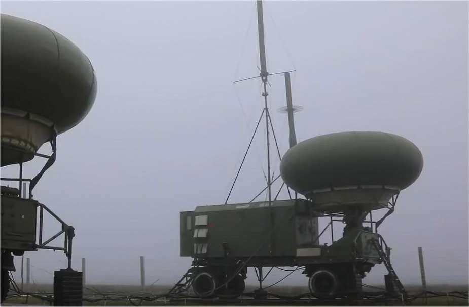
The fog photograph. Two dome trailers side by side in thick fog, the nearer one a green equipment van on a wheeled chassis with a green egg-shaped radome mounted on top at the front, a guyed lattice mast beside it with a cross-arm and a disc element, a second mast behind. The second dome at the left edge is the same type of trailer. Photographer and location are not known to me. That there are two trailers is interesting; see the hardware section. [DOCUMENTED description; origin unknown]
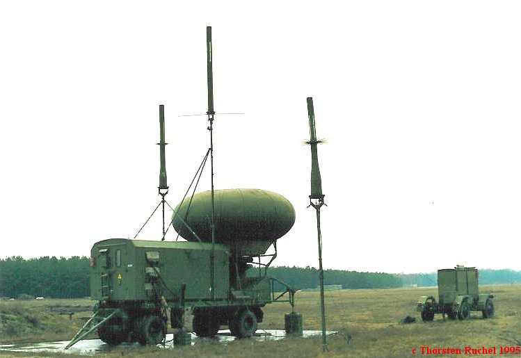
The Ruchel photograph. The same type of trailer on a grass field with a pine forest behind: the dome on top of the van, three tall slim masts at different heights around it, one of them dressed with a ring of whiskers or wires near its top, and a second smaller box trailer to the right. It carries the visible credit "c Thorsten Ruchel 1995" in red, and I credit it in the Sources section below. The location is not stated. [DOCUMENTED credit; location unknown]
The composition slide. A Russian slide titled "Радиотехническая система ближней навигации дециметрового диапазона РСБН-4Н(М)" with a colour photograph of a trailer on stubble grass and a Russian text block listing the components. The caption text is part of the image and is left as it is. I translate it below. [DOCUMENTED]
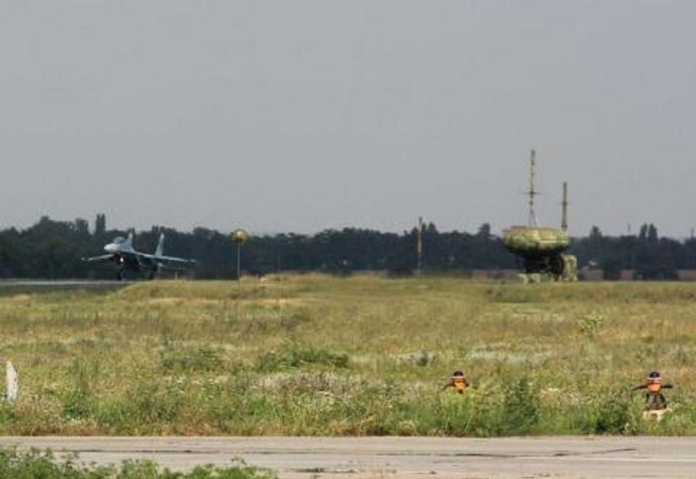
The Su-27 at the airfield. A Sukhoi Su-27 on its landing run, a dome-on-trailer beacon with two masts at the right of the picture, and two small orange-and-white objects in the foreground grass that look like runway-edge or approach markers. No caption, no photographer, no airfield name. It shows what the layout looks like from the runway side: the aircraft, the beacon about a few hundred metres from the strip, and the clear line of sight between them. Which airfield this is I do not know, and I have not tried to guess. [DOCUMENTED description; origin unknown]
The airfield equipment infographic. A Russian-language illustration of the radio-technical equipment ("радиотехническое оборудование", РТО) of an airfield, with the watermark vk.com/avialetuchka. It shows the RSBN-4N dome beside the runway together with the landing beacon group, marker beacons, radars and direction-finders, with distances in metres. It is the best single picture of where everything sits, so it is discussed in detail below. [DOCUMENTED; the infographic is a simplified teaching picture, not a survey]
The MiG-21 cockpit page. A page titled "RSBN - NAVIGATION / MiG-21" in German, from a flight-simulator guide: four screenshots of cockpit panels with numbered steps. Its source is not known to me. It shows a simulated MiG-21 cockpit, not a real photograph, but it is faithful enough to show where the controls are and what they are called. It is used in the cockpit section. [DOCUMENTED description; origin unknown]
WHY THE SYSTEM EXISTS: THE PROBLEM IT SOLVES
Before satellites, a combat aircraft had four ways to know where it was: look out of the window, use a compass and a stopwatch and a map (dead reckoning), use a self-contained inertial or Doppler system that drifts over time, or listen to a radio navaid. Dead reckoning and inertial systems drift; the error grows steadily with time. Windows are useless in cloud or at night. A radio navaid gives a fix that does not drift, which is what the other systems need in order to be re-zeroed.
Soviet planners wanted a fix that (a) worked in all weather, day and night; (b) gave both direction and distance from one single ground station, so no pair of stations or intersecting lines was needed; (c) was accurate enough to bring a fighter or bomber to a given point or onto a runway; (d) let the airfield see the aircraft; and (e) was independent of the Western standards, so that the whole thing could be built, supplied and kept running inside the Soviet bloc. The Polet sales sheet says exactly this in a polite way: the signal format "is not specified by ICAO, but principal specifications are met or exceeded". [DOCUMENTED]
The textbooks name the type of system "polar", "rho-theta" in English: a position is given by a distance (rho, ρ) and an angle (theta, θ) from a known point. Western equivalents are VOR/DME and TACAN, which also give rho and theta. The Soviet textbook comparison states the difference in design: VOR/DME is built on the metre-wave band and measures angle by comparing the phase of two tones; RSBN is built on decimetre waves and measures both angle and range by timing pulses. The same textbook calls RSBN "a complex system of short-range navigation and landing" because it combines position finding, a landing mode and ground observation in one set. [DOCUMENTED, studfile classification chapter]
Two further aims of the Soviet design are visible in the lists of functions. First, RSBN lets aircraft navigate relative to each other ("inter-aircraft navigation", режим межсамолётной навигации, "Встреча" or "Rendezvous" in some sets): one aircraft carries the equivalent of a beacon, and another measures range and bearing to it, so a group can fly in formation or rejoin in cloud. Second, the ground side can ask any aircraft to identify itself, by radio request, and mark it on the controller's screen. Both are described below. [DOCUMENTED]
HOW IT WORKS: THE BIG PICTURE
The ground beacon sends out three kinds of signal, all on one "channel" (a frequency-and-code combination, chosen by number):
The aircraft carries a receiver that listens for the beam and the reference pulses, and a small transmitter (the "interrogator", запросчик дальности) that sends the range request. From these two it derives azimuth and range, and displays both on a combined indicator. [DOCUMENTED]
The key design idea is that everything is time. The beam passes the aircraft once per revolution; the time between the "north" mark and the moment the beam hits the aircraft is the azimuth. The delay between the aircraft's interrogation and the beacon's reply is the range. No phase measurement, no tone filtering, no magnetic reference.
THE AZIMUTH CHANNEL
The antenna. A directional antenna in the dome produces, in the horizontal plane, two narrow lobes lying close together with a sharp null between them. The null is much narrower than either lobe. The antenna is turned by a motor at a constant 100 revolutions per minute, 1.66 per second, so the whole pattern sweeps past the horizon every 0.6 seconds. [DOCUMENTED, MGTU textbook and Skrypnik]
Why two lobes and a null instead of one beam? Because a sharp null is much more precise than the peak of a single wide lobe. If you point your ear at a sound source, you cannot easily tell the exact peak of loudness; if you listen for the moment the sound drops to zero between two sources, you can. Russian Wikipedia puts it this way: the azimuth is fixed by the dip between the lobes, which is far narrower than the lobes themselves, giving a high accuracy. [DOCUMENTED]
An aircraft that sits somewhere around the beacon sees, from its position, a "double bell" envelope in the received signal strength as the pattern sweeps across it. A circuit in the aircraft's receiver converts one feature of that envelope into a short azimuth pulse (азимутальный импульс). The textbook says the azimuth pulse is formed from the first bell's trailing edge at the half-amplitude level. Details of exactly which edge is used differ in how the sources describe it, and I have not seen the circuit diagrams, so I leave it at "formed at a fixed point in the pattern". The pulse arrives at the aircraft at 1.66 pulses per second. [DOCUMENTED]
The reference signals. A separate pulse transmitter drives an omnidirectional antenna, which sends two coded pulse series per revolution. The "35" series sends 35 coded pulse groups per revolution, evenly spaced; the "36" series sends 36. Because one series has one more group than the other over the same time, the two groups' timing slides against each other during the revolution, and they line up exactly once per revolution – at the instant the antenna's null direction points to true north from the beacon. The aircraft receiver watches for this coincidence and uses it as "time zero" for its stopwatch. This is the north signal (сигнал «Север»). [DOCUMENTED]
The beauty of this scheme is that the "north" mark is radiated from an all-round antenna, so every aircraft in range hears it at the same moment (plus a tiny propagation delay), while the beam hits each aircraft only when it sweeps past. The interval between the two is therefore a clean measure of the bearing, independent of range to first order.
The calculation. At 100 rpm the beam turns 600 degrees per second, or 1 degree in about 1.67 milliseconds. If the interval from "north" to the azimuth pulse is t, the azimuth is simply A = 600 × t (in degrees, with t in seconds), and the airborne block that measures it (the "azimuth measuring block", БИА) just counts. A bearing of 90 degrees (the aircraft is due east) gives an interval of 0.15 seconds. A bearing of 0.25 degrees corresponds to about 0.42 milliseconds, which is the timing budget for the quoted accuracy. [ESTIMATE, from the 100 rpm figure; the formula itself is the textbook's A = Ω·t]
Because the beacon turns at a constant rate, the whole system rests on that rate being steady. The beacon has an automatic speed-stabilisation system for the azimuth antenna drive (an electric-machine amplifier, a DC motor with a tachometer and a regulation unit) and a separate monitoring and alignment set (контрольно-юстировочная аппаратура, КЮА) with a remote receiver that checks the north zero. A student thesis at South Ural State University (2023, written with the maker, Polet) is devoted entirely to a test program that simulates the beacon's "north", "36", "35" and "180" signals so that the drive column's sensors and rotation-speed instability can be tested; that is a good sign of how critical the steadiness of the turntable is. [DOCUMENTED; the thesis summary is the source for the signal names, the text for the drive details is from a lecture on the 4N azimuth channel]
The coded reference pulses and channels. The reference pulse groups are not single pulses but coded, and the code is how a channel is told apart from its neighbours. A lecture slide on the RSBN-4N azimuth channel lists four code variants for each series, with different time offsets in microseconds, and I read this as the code part of the "frequency-and-code" channel. Exactly how the 88 channels are made up of frequency and code combinations I did not find spelled out. [SINGLE-SOURCE and incomplete]
Unlimited aircraft. Because the azimuth signal is a one-way broadcast, any number of aircraft can use it at once, exactly like a lighthouse. The documents say the number of aircraft served by the azimuth channel is "unlimited". The range channel is different (see below). [DOCUMENTED]
The nickname. Russian Wikipedia records that because of the large, quickly rotating antenna inside the dome, RSBN ground stations have the slang name "стиральная машина" (washing machine). That explains the dome too: the 100 rpm antenna would tear itself around in wind and weather and would be unsafe to be near, so it sits inside a protective radome. The same page uses that as the reason for the cover. [DOCUMENTED]
THE RANGE CHANNEL
The range channel works like the radar equation turned inside out: the aircraft asks, the ground answers, and the aircraft times the round trip. This is a "secondary" system (a transponder system), not a radar echo. The beacon does not look for aircraft; it only answers those that ask.
Step by step.
I saw, in a search-engine summary of a Russian lecture text which I could not open directly, that the fixed delay subtracted is 183.4 microseconds and that identification on the indicator uses a second pulse after a 50 microsecond delay (equivalent to 7.5 km on the display; 50 µs ÷ 6.67 µs per km round trip is 7.5, so the two numbers are at least consistent with each other). I treat both as [SINGLE-SOURCE, secondary]; the structure (fixed reply delay, subtracted on board) is documented, the specific numbers are not independently confirmed.
Why a transponder rather than echoes? A 10 kW class ground transmitter and a 1 kW class aircraft transmitter (the Eurocontrol document lists 70 dBm ground and 60 dBm airborne, i.e. 10 kW and 1 kW peak [SINGLE-SOURCE; ESTIMATE for the conversion]) cannot pull a useful echo off a fast fighter at 400 km, but they can easily exchange coded pulses. In a transponder exchange each leg is a one-way trip, so signal strength falls with the square of distance on each leg; a radar echo has to pay that price twice over, falling with the fourth power. [BACKGROUND]
The catch: capacity. The ground beacon can only answer so many interrogators at once. The 4N table gives the range channel a throughput of 100 aircraft, against unlimited for azimuth. [DOCUMENTED, Kolomiets] That is a long way above anything a single airfield needs, but it is a real limit that matters for the saturation discussion in the vulnerability section.
Interrogation tied to the beam. Russian Wikipedia states that the airborne equipment is built so that the range interrogation can only be sent at the moment the aircraft is illuminated by the azimuth beam, and it is tied to the reference "36" pulse series. This lets the ground work out where on the compass each interrogation came from, because it knows the antenna's pointing angle at that moment. That is what makes the "ground observation" function possible. It also tells us the interrogation is not a continuous stream of pulses but arrives in bursts at the beam rate. [DOCUMENTED for the statement; the details of how the airborne equipment then keeps a smooth range readout between the beam passes are not given in anything I read. I suspect a tracking and memory arrangement. [SPECULATION]]
SEEING THE AIRCRAFT FROM THE GROUND
The beacon also lets the airfield see aircraft that use it. The mechanism is neat and cheap:
This is a primitive but robust secondary-radar-like function with no code book and no encryption. It is also one of the characteristics that make the ground beacon a rather open system, discussed under vulnerability.
THE MODES IN FLIGHT: NAVIGATION, ORBIT, LETDOWN AND LANDING
The airborne set has a mode switch with positions that appear, in the simulator page supplied by Robert, as Land / Navigation / Descend (in Russian the modes are "Навигация", "Посадка" and the descent or "cloud-breaking" mode, "пробивание облачности", "ПО"). The Soviet textbook on the RSBN-2S says the set has "two main operating modes: navigation, and landing including the cloud-breaking manoeuvre". [DOCUMENTED]
Navigation mode. The set tracks the beacon's azimuth and range continuously. The pilot's indicators then show a bearing of the aircraft from the beacon (not a bearing to the beacon, an important difference from a Western ADF or VOR "to" needle) and the slant range in kilometres. The pilot can then do three kinds of navigation, listed by the Soviet textbooks: [DOCUMENTED]
On the early RSBN-2S the computing device (the "counting and solving device", СРП) and the "direct-reading range and azimuth instrument" (ППДА, one for the pilot and one for the navigator) do this. The later RSBN-6S, with block names like БВН (navigation computing block) and БВП (landing computing block), adds a digital-style computer; the Soviet table for the 6S lists the accuracy of the autonomous mode too, discussed below. [DOCUMENTED, Russian Wikipedia's block lists]
The signal for passing a target. The 2S textbook also lists "indication of the moment of overflight of a given target", meaning the system can ring or light up as the aircraft passes over a preset point, usually computed as a range and azimuth from the beacon. For a bomber this was the original "bring the aircraft to any specified point" function. [DOCUMENTED]
Letdown mode (descent through cloud). A letdown, in Western terms an instrument "procedure descent", is done in RSBN mode as a cone: the pilot is at some height at a distance from the beacon, in the descent mode the set computes a reference descent profile as a function of the measured distance, and the pilot follows a needle to stay on it. The DCS community figures for the MiG-21 (from the aircraft manuals, as quoted on the ED forum) are: the letdown starts at about 132 km from the airfield at 10,000 m, ends at a floor of about 21 km at 600 m above the airfield, with an average gradient of about 4.8 degrees; for the L-39 trainer the top is 8,000 m rather than 10,000 m. The pilot must set the airfield's pressure on the barometric altimeter correction. [SINGLE-SOURCE: a simulator forum thread by two experienced MiG-21 community members, who quote the manuals; the figures are consistent with the textbook picture but I did not see the manual]
Landing mode. Here the airborne set switches off its dependence on the navigation beacon's azimuth and listens instead to the landing beacon group, PRMG, described in its own section below. In the landing mode the pilot has separate channel settings for the PRMG: the simulator page shows two channel windows side by side, labelled "НАВИГАЦИЯ" and "ПОСАДКА", each set with its own knob. [DOCUMENTED]
Autonomous (dead-reckoning) mode. If the beacon's signal is lost, the 6S runs on its own computation. The Soviet figures quoted in the MiG-21 thread are errors of no more than about 0.8 km per minute in distance and 0.5 degrees per minute in azimuth at 800 km/h, versus 200 m and 0.25 degrees "total" when it is receiving the beacon (the "radio-correction mode", where the beacon's signal corrects the computer). That is the practical reason RSBN is an integrating navigation aid, not just a beacon receiver: the beacon re-zeroes an onboard dead-reckoning computer. [SINGLE-SOURCE, forum quoting RSBN-5/6 manuals]
CHANNELS: 88, 40, 10 AND WHY THE NUMBERS DISAGREE
A "channel" is a number the pilot dials to match the beacon he wants. Different documents give different numbers, and they are not all talking about the same thing.
Conflict: the azimuth frequency band. The ppt-online lecture on the RSBN-4N azimuth channel gives the pulse transmitter (reference signals) 873.6 to 903.7 MHz and the continuous (azimuth) transmitter 905.1 to 935.2 MHz. The Kolomiets table gives the azimuth channel 873 to 935 MHz overall. The avsimrus wiki prints "873.6-812.8", which is a typographical error (the 812.8 belongs to the interrogation band). The Russian MGTU textbook states the whole system uses 720 to 812.8 MHz for aircraft-to-ground and 873.6 to 1000.5 MHz for ground-to-aircraft, with 720 rather than 772 as the lower edge. I treat 772 as the 4N value (three sources) and 720 as an outer allocation for the whole RSBN family. [source conflict, flagged]
What the UHF band means for physics. A frequency of 900 MHz has a wavelength of about 33 cm. At such short wavelengths the signal travels in a straight line, is not bent by the ionosphere, and is blocked by the horizon. It also allows a small, practical antenna: a lobe that is a few degrees wide can be made with a dish or array about as big as the dome. [ESTIMATE for the wavelength; BACKGROUND for the rest] The band 873 to 1000 MHz also overlaps the GSM-900 mobile telephone band (about 880 to 960 MHz), and the Eurocontrol paper on RSBN and PRMG notes known incompatibilities between RSBN and deployed commercial communications systems, handled by geographic separation. [DOCUMENTED, Eurocontrol 2009; the GSM overlap is my own observation, BACKGROUND]
THE PRMG: GETTING DOWN TO THE RUNWAY
RSBN gives position, not a landing. Landing is by a separate set of beacons beside the runway, the посадочная радиомаячная группа (ПРМГ). Textbook versions: PRMG-4 (and the PRMG-4K and 4KM), PRMG-5 (PRMG-76U), PRMG-76 and PRMG-76U; the English-language Polet sheet advertises "PRMG-76UM", the modernised one. The group serves, per the textbook, "aircraft equipped with RSBN airborne equipment, to the runway day and night in weather minima of category 1 and 2, in manual, director and automatic control". [DOCUMENTED]
The PRMG has three parts:
The physics of the course and glide needles. The KRM and GRM work in the same way as each other and are close cousins of the Western ILS. Each creates, in space, two overlapping lobes of radiation. The signal in one lobe is modulated with 1,300 Hz tone and the signal in the other with 2,100 Hz. The airborne receiver compares how strong each tone is. In the course beacon, the left lobe has 2,100 Hz and the right lobe 1,300 Hz; if the aircraft drifts right of the centreline, the 1,300 Hz tone dominates, and the course needle swings; at the equi-signal line the two tones are equal and the needle is centred. The glide beacon does the same in the vertical plane: 1,300 Hz in the upper lobe, 2,100 Hz in the lower. The pilot "holds the aircraft in the position where the course and glide bars cross in the centre of the instrument". [DOCUMENTED]
That is the same principle as an ILS localizer and glide slope (a difference in depth of modulation, "DDM", between two tones, 90 and 150 Hz in the Western system). The Soviet version differs in tone frequencies and in being on UHF channels that are the same as the RSBN azimuth beacon channels: "the working frequencies of the KRM are completely identical to those of the azimuth beacons". So the same airborne receiver covers both. [DOCUMENTED for the Soviet side; the ILS statements are BACKGROUND]
Typical performance numbers (from the ED MiG-21 thread, quoting the manuals): the localizer total signal region about ±15 degrees (±18 typical), range about 45 km (75 km or more typical); the glide path about 18 km (30 typical); the glide angle chosen from 2 to 4 degrees, with 2°40′ typical for the MiG-21; instrument "reading zone" 4 to 6 degrees each side of the localizer centre. The localizer's instrument reading is two or more times coarser than its radio accuracy of 0.25 degrees, because of the indicator's own error. Approach lateral error for CAT I about ±10.5 m and CAT II about ±7.5 m at the threshold. [SINGLE-SOURCE, simulator-community forum]
The coverage numbers in the Soviet textbook. For the RSBN-2S working with the PRMG-4, the localizer range at 300 m height is about 20 km and at 1,000 m about 80 km; the glide beacon at 300 m is 20 km; the landing range finder at 1,000 m is 50 km. [DOCUMENTED, Tulin's RSBN-2S page; different generation of equipment from the MiG-21 figures, so the numbers differ]
The station layout at an airfield. The infographic supplied by Robert shows this arrangement, and its numbers match the textbooks: the RSBN beacon ("Маяк (РСБН)") is shown 300 to 600 m from the runway axis and up to 1,200 m from the runway centre; the glide beacon (ГРМ) 120 to 180 m from the axis and 250 to 450 m from the touchdown point; the course beacon (КРМ) 400 to 1,100 m beyond the end, with a "ДКРМ+ГРМ" box labelled as the PRMG-5 set. The textbook says 500 to 1,200 m for the course beacon and 200 to 450 m for the glide beacon, so there are small differences in the range figures: 400 to 1,100 against 500 to 1,200 m, and 250 to 450 against 200 to 450 m. The infographic is a simplified teaching picture and I treat the textbook values as the rule and the picture as illustration. [source conflict, flagged, minor]
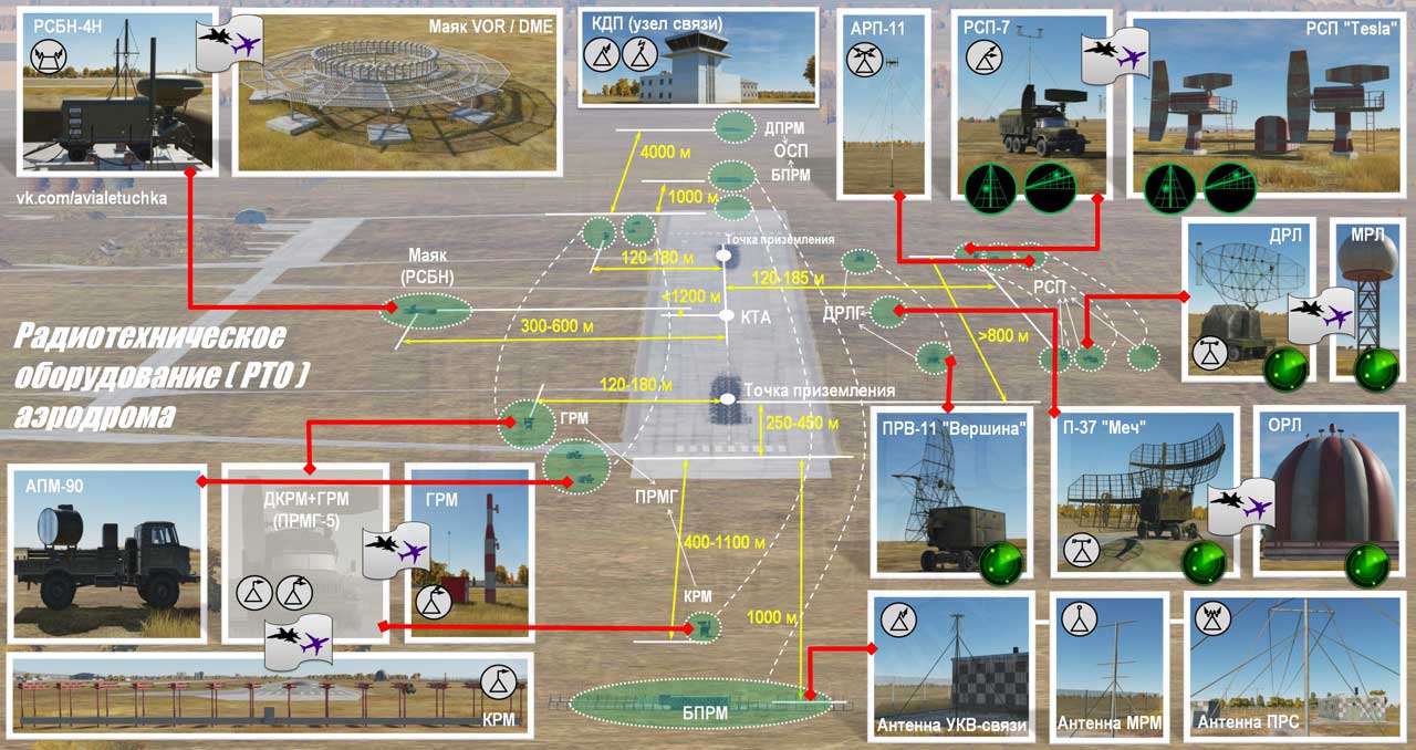
The same picture shows, in addition to the RSBN and the landing group, the other things a Soviet airfield carries: a VOR/DME beacon (for foreign or civil traffic), the command post (КДП), a radio direction finder (АРП-11), several radars (РСП-7 and a "Tesla" set for precision approach, a long-range radar, "ПРВ-11 Вершина", "П-37 Меч" and others) and the marker beacons at 1,000 m and 4,000 m from the threshold (ДПРМ, БПРМ, ОСП). That is the real setting: RSBN is one of several redundant aids, not the only one. The original text names are visible in the image and I have not tried to identify every box. [DOCUMENTED for what is labelled; interpretation of the individual radars is outside this article]
HOW RSBN COMPARES WITH VOR/DME, TACAN AND ILS
This is the comparison table in prose. [BACKGROUND for the Western side unless stated; DOCUMENTED for RSBN]
VOR (VHF omnidirectional range). 108 to 118 MHz (metre waves), standardised by ICAO, civil. It sends two 30 Hz signals: one that is the same in all directions and one that rotates, so the phase difference between them is the aircraft's bearing. It refers to magnetic north. Typical accuracy is a degree or two; the accuracy is limited by site effects from terrain and buildings. RSBN is a time-measuring, decimetre-wave system with a stated accuracy of 0.25 degrees (azimuth channel; the pilot's instrument is coarser) and refers to true north. The Soviet textbooks take pride in that: "RSBN-4 surpasses all foreign analogues in accuracy but is incompatible with them in signal type". [DOCUMENTED]
DME (distance measuring equipment). 962 to 1,213 MHz, pulse-pair interrogation by the aircraft, reply by the ground transponder after a fixed 50 microsecond delay; accuracy about 0.2 NM (370 m) in the civil standard. RSBN's range channel is the same idea (a transponder timed round trip), but on different frequencies and codes, so DME and RSBN avionics cannot talk to each other. Its accuracy of ±200 m is a little better on paper than civil DME's. [DOCUMENTED for RSBN; BACKGROUND for DME]
TACAN. The military Western system that combines azimuth and range in one beacon, in the same 962 to 1,213 MHz band as DME. It uses a rotating antenna pattern with two modulations (15 Hz and 135 Hz) to measure bearing by phase, rather than timed pulses. Concept: TACAN is a much closer cousin of RSBN than VOR is, since both are military, one-station azimuth-and-range systems that fit on a vehicle. RSBN's distinct choices are the time-interval azimuth method and the separate landing mode through PRMG. [BACKGROUND; the cousin comparison is my own interpretation]
ILS (instrument landing system). Localizer 108 to 112 MHz and glide slope 329 to 335 MHz, with a 90 Hz and 150 Hz difference-of-modulation. The PRMG is the Soviet equivalent in principle (two lobes, two tones, centre-line where they equal). The Soviet civil counterpart of ILS was a different set, "СП-50" (SP-50) in the metre band, and a forum source says the SP-50 is not the same as the PRMG. RSBN/PRMG is the military and airfield-integrated one. [DOCUMENTED for PRMG; SINGLE-SOURCE for SP-50]
Where RSBN does more than the Western systems. It integrates azimuth, range, landing, ground observation, identification and the dead-reckoning correction in one family. The Soviet textbook specifically notes the "possibility of ground observation of the air situation, determination of coordinates and navigation identification of the aircraft" as the distinguishing feature. [DOCUMENTED]
Where it does less. It is not standardised outside the Soviet bloc, so Western airliners cannot use it. After the Soviet Union ended, RSBN "did not get wide distribution in civil aviation" (avsimrus wiki), and Russian civil aviation now relies on VOR/DME (Russian Wikipedia). It needs airborne equipment that is wired into the aircraft's own navigation computer, so retrofits are expensive. And it has no digital data link and no authentication. [DOCUMENTED for Russia's current split; the retrofit remark is my own comment]
THE GROUND HARDWARE: WHAT IS IN THE TRAILER AND AROUND IT
The ground beacon is a mobile-looking, though normally fixed, set. Its parts, from the Kolomiets textbook, the Skrypnik textbook, the Polet sheets and the composition slide, are as follows.
The equipment trailer (аппаратный прицеп, "аппаратная"). A closed wheeled box van on a two-axle trailer chassis that carries the transmitters, receivers and control gear. The dome sits on top of the front part. Inside are the radio transmitting and receiving units, the pulse-navigation equipment (ИНА, импульсно-навигационная аппаратура), the monitoring and alignment equipment (КЮА), the equipment that stabilises the azimuth antenna's speed, the plan-position display (ИКО), the remote-control interface and the power and ventilation panel. Photographs show jacks at the corners, a ladder and folded cable runs, so the trailer can be levelled and fixed in position. [DOCUMENTED]
The antenna dome. The egg-shaped radome (the "washing machine") covers the rotating azimuth antenna that turns at 100 rpm. The antenna is fed by the continuous-wave transmitter. The dome stays the same in the pictures of the old and the new versions, so I treat the antenna group as unchanged between 4N and 4NM. [DOCUMENTED for the function; the "unchanged" remark is an inference from photographs, [ESTIMATE]]
The masts. Guyed slender masts stand around the trailer. The textbooks call the antenna system the "антенно-фидерная система (АФС)" and list, for the azimuth channel, two transmitting antennas: the reference-signal antenna (omnidirectional, for the "35", "36", "north" and for the range reply and "180" signals) and the azimuth continuous antenna inside the dome. The masts in the photographs have different heights, cross-arms and discs, which fits several separate roles: reference transmission, range receive and transmit, and the monitoring path. I could not find a source that says which mast does what. Do not read the individual mast roles into the pictures. [DOCUMENTED that there are separate omni antennas; the individual mast roles are [UNVERIFIED]]
The monitoring point (КВП, контрольно-выносной пункт). A small receiving unit installed some distance from the trailer, used to check the beacon's own north zero and signal quality from outside. This is the "remote monitoring receiver" of the KYuA that appears in lecture slides for the RSBN-4N (block "БР-003" receiver and the north-zero block "БК-006"). The second, smaller box trailer visible on the right in the Ruchel photograph could be this or another auxiliary unit. I do not know which. [DOCUMENTED that the КВП exists; the identification of the small trailer is [SPECULATION]]
ВИКО (выносной индикатор кругового обзора). The remote circular-view indicator: a plan-position screen that shows every aircraft interrogating the beacon at its azimuth and range, installed at the command post (КДП), up to about 30 km from the beacon. It is, in effect, a repeater of the display in the trailer. The slide supplied by Robert lists it as the second component. [DOCUMENTED] The tube is an ordinary radar-type CRT display; for the physics of such tubes see CRT Displays.
ТУ-ТС (блок дистанционного управления). The remote control unit. In the Russian text of the slide: "Блок дистанционного управления ТУ-ТС". The letters are read by the textbooks' practice as "ТУ" for телеуправление (remote control) and "ТС" for телесигнализация (remote signalling); the English Polet sheet calls it the "remote control and signalling unit (RC&S)", which supports that reading. The main control mode is remote from the command post, and the backup is local, at the trailer. [DOCUMENTED, Kolomiets table; the letter expansion is [UNVERIFIED] but consistent with Polet's English]
Power. The slide lists a "Дизельная электростанция типа ЭД-16", a diesel power station of type ED-16, and states "Преобразователь сети ВПЛ исключен" (the VPL converter removed). The Kolomiets textbook for the earlier RSBN-4N lists "two diesel power stations and a VPL-30 converter" and a power draw of 30 kVA. The student-document search summary listed "ЭД-30" reserve generators for the older set, and the Polet English sheet shows a figure of "16" next to the power consumption, but the text of that PDF is garbled and I could not read it reliably. Soviet diesel generator sets of the "ЭД-" series are conventionally named by their power in kilowatts (the common ED-30 is a 30 kW set), which would make the ED-16 a 16 kW set; that agrees with a drop in power need on the 4NM, and I treat it as a plausible reading. [source conflict: 30 kVA with ED-30 and VPL-30 converter (4N) against ED-16 and no converter (4NM); the kW naming of the ED series is BACKGROUND; the 16 kW reading is [ESTIMATE]] The ВПЛ converter, as I understand its role, changed the generator's output frequency or voltage for the beacon; its removal is documented, its exact function in the old set is [UNVERIFIED].
Environmental and size figures. Polet's English sheet: operating temperature minus 50 to plus 50 °C, humidity up to 98% at 35 °C, supply 380/220 V 50 Hz, deployed size about 7.5 × 5 × 10 m (the masts included), stowed about 9.78 × 2.6 × 3.8 m, weight of the control room about 7,000 kg (the table wording about a reduced weight of 4,300 kg is garbled and I do not use it). [SINGLE-SOURCE, from a damaged PDF; use with care] The ready-to-work time: 5 minutes in the Kolomiets table, 1.5 minutes in the avsimrus wiki. [source conflict, flagged]
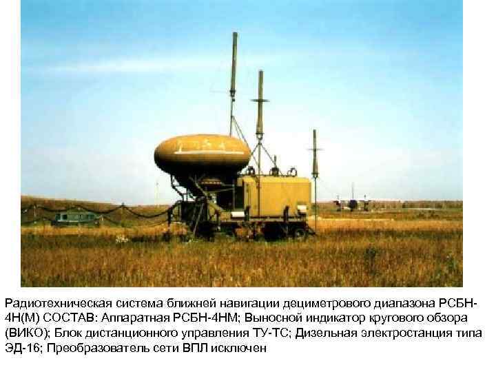
The slide supplied by Robert, translated: "Short-range radio navigation system of the decimetre band, RSBN-4N(M). COMPOSITION: RSBN-4NM equipment set; remote circular-view indicator (VIKO); remote control unit TU-TS; diesel power station of the type ED-16; the VPL network converter is excluded." [DOCUMENTED; translation mine]
Two domes in one picture. The fog photograph shows two dome trailers next to each other. A set with a spare beacon is plausible: the RSBN-4N set includes two diesel stations, and the beacon is critical to airfield operations, so a spare is reasonable. The textbooks I read do not, however, say that a second beacon is part of the standard set. [SPECULATION; two trailers appear in one photo, no source says why]
Siting. At an airfield the beacon is placed 300 to 600 m from the runway axis and not more than 1,200 m from the runway centre (some texts say 1,000 m). Along a route it is placed so that the aircraft's track misses the cone of silence over the beacon: the textbooks give a "non-working zone" of ±45 degrees around the vertical above the beacon. [DOCUMENTED] For a flat cone like that, the unusable circle on the ground at a given altitude has a radius about equal to the height: at 5,000 m the aircraft loses the beacon within about 5 km of passing over it; at 250 m it is about 250 m. [ESTIMATE, tan 45° = 1] That is why the standard advice is to offset the beacon from the flight line by twice the dead zone radius.
THE COCKPIT SIDE: WHAT THE PILOT SEES AND TOUCHES
The page supplied by Robert shows a simulated MiG-21 and numbers six items. Translated from German, they are: (1) switch to RSBN; (2) select the RSBN channel; (3) select the PRMG channel; (4) select the radio channel (the voice radio, a separate set); (5) set the navigation mode; (6) shows distance to the airfield in km; and at the bottom, "take RSBN channels from the kneeboard". [DOCUMENTED, the page's own text; simulated cockpit]
In plain terms: a switch at the left puts the instrument systems onto RSBN; a small panel carries two channel selectors (НАВИГАЦИЯ and ПОСАДКА) with two-digit windows; a mode switch on a console below the instrument panel chooses between landing, navigation and descent; a three-digit mechanical counter on the instrument panel shows the slant range to the beacon in kilometres. The bearing and the course and glide needles are shown on the combined "navigation-flight instrument" (НПП) that the DCS forum thread refers to. Two indicator lights (labelled "К" and "Г" in the simulator, for course and glide) change when stable PRMG signals are received. [DOCUMENTED for the panel; SINGLE-SOURCE for the lamp function, from the sim manual summary]
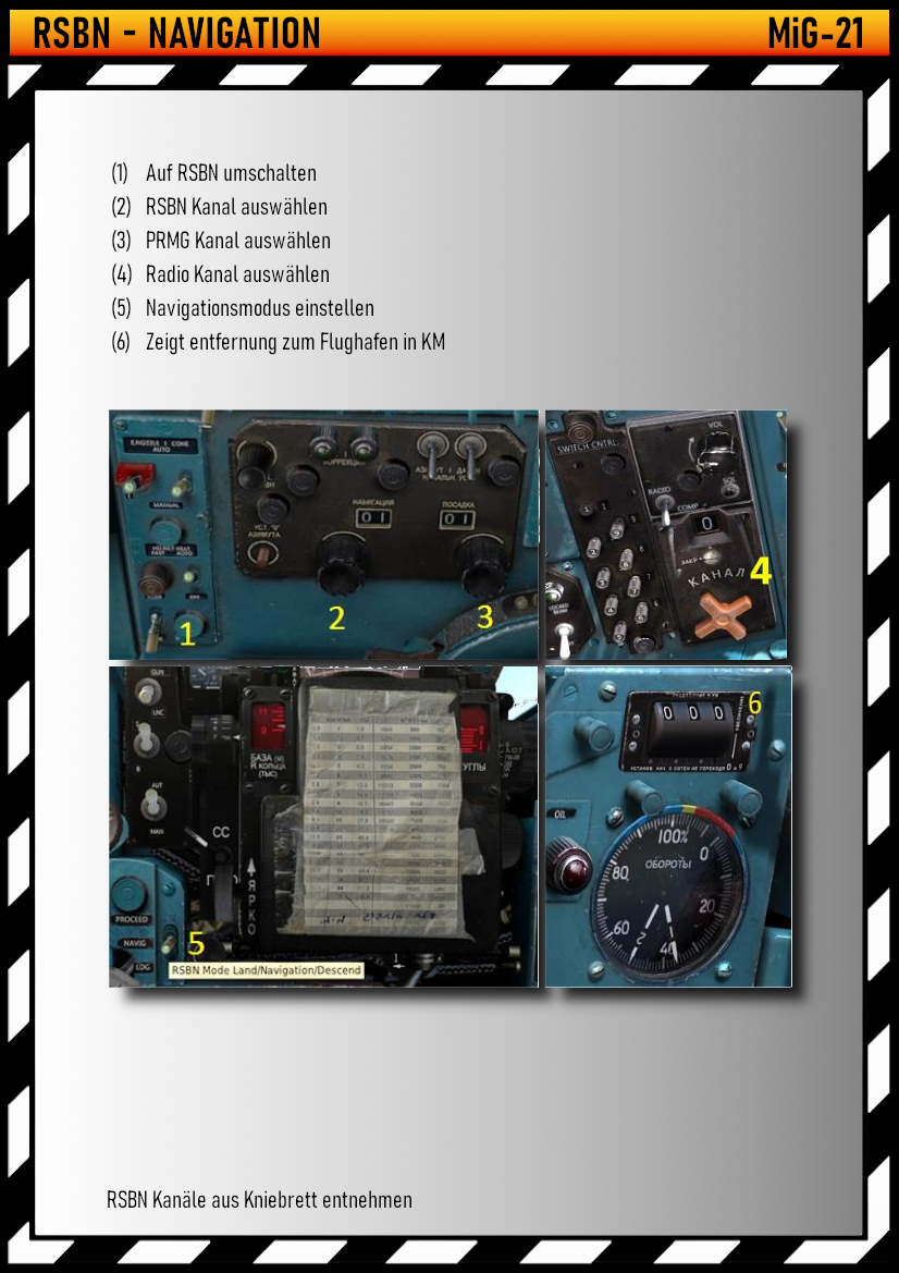
The plastic-covered paper card visible in the lower-left panel of the page is the kneeboard channel list. The page's own caption points at it. In the real MiG-21 manual setup, a list of beacons with channel numbers is one of the things the pilot takes on every flight. [DOCUMENTED for the simulator page; the real-world practice is [SINGLE-SOURCE], forum]
The MiG-21 is only one example. Other Soviet types carry other members of the same airborne family, but the pilot's task is the same: dial a channel, pick a mode, watch azimuth and range. [see the aircraft section for what is and is not documented]
WHICH AIRCRAFT CARRY IT
The airborne sets are a family. Russian Wikipedia lists, in order of generation: RSBN-2S "Svod" (with its units SPAD-2 receiver, SZD-M interrogator, BIA azimuth block, BD range block, ShchU control panel and the SRP computer, and the pilot's and navigator's PPDA indicators), RSBN-2SA "Svod-Struna", RSBN-2SV, RSBN-5S, RSBN-6S "Romb" (a monoblock with BIAD azimuth and range block, navigation and landing computing blocks and a code-switching panel), RSBN-6SV, RSBN-7S, RSBN-PKV, "A-312", "A-321", "A-324 Klistron" (with processor block A-324-016) and RSBN-85 and 85V. Another textbook list gives airborne sets RSBN-6S, 7S, A-312, A-317, A-323, A-324 and A-331 (RSBN-85). [DOCUMENTED]
Which sets fly on which aircraft is where the public record gets thin. What I found:
For the RSBN-4N, the first forum poster states the rule that "all Soviet short-range radio navigation sets work with RSBN-4: RSBN-5, RSBN-36, RSBN-6S, A-312 etc." [SINGLE-SOURCE] So the ground beacon is generic and the aircraft sets are interchangeable across generations, which is why a single beacon can serve an entire air regiment of mixed types.
Gap: a proper table of airborne sets by aircraft would be a good sub-article. I did not find a reliable single list.
WHERE IT IS USED TODAY
Russian Wikipedia says that in Russia RSBN "is now used mainly only in military aviation", while civil aviation uses VOR/DME. [DOCUMENTED] The Russian authority's own airfield-fitness standards for experimental-aviation airfields (Minpromtorg order 1215 of 30 December 2009) still list RSBN as an element, with a flight-check requirement that the RSBN-4N has a range of 200 km at 3,000 m height, in remote and local control modes. [DOCUMENTED, Consultant.ru] The beacon is also in production and export: OPK reported in November 2014 that Polet was completing deliveries of "RSBN-4NM and PRMG-76UM" to Vietnam, calling them a new generation with "no analogues in Russia" because of the microprocessor base and saying only Polet in Russia makes them. [DOCUMENTED, AEX.ru]
The RSBN family is also still in service in many former Soviet and Warsaw Pact air forces and in some others that bought Soviet types. I did not assemble a list of countries or sites. [BACKGROUND]
UKRAINE WAR RELEVANCE: WHAT IS ACTUALLY SOURCED
Very little. Here is what exists.
Nothing in the sources lets me say how RSBN has performed in the war.
JAMMING AND VULNERABILITY
Everything in this section is reasoning from the system's published design, because I found no open source that tests RSBN against jamming or spoofing. The facts the reasoning rests on are documented; the conclusions are mine. [BACKGROUND, ESTIMATE and SPECULATION as marked]
What helps it. RSBN is independent of satellites, so GNSS jamming does not touch it. The azimuth beam is narrow and rotating, which gives it some spatial resistance to noise from a single direction. The ground transmitter is much stronger than any satellite signal at the ground: about 10 kW peak against a GNSS signal of the order of 10 to the minus 16 watts at the receiver, a difference of a hundred million million times or more. [ESTIMATE; Eurocontrol power figure and the typical GNSS signal level, BACKGROUND] For a jammer to override a beacon signal, it has to be much closer to the aircraft than the beacon is, or to be a lot more powerful than the transmitter, which is a very different job from jamming a weak satellite signal.
What hurts it. The following are design features, not demonstrated failures.
The right summary is that RSBN is robust against the kinds of interference that cripple GNSS, and fragile against anything specifically designed to spoof or locate it, but this is an assessment, not a test result.
WHAT IS NOT KNOWN
SUB-ARTICLE GAPS
These topics deserve their own pages and are only touched here:
RELATED ARTICLES
SOURCES
Own working: wavelengths, timing per degree, range per microsecond, the dead-zone radius, power conversions and the GNSS comparison are arithmetic from published numbers and marked as estimates.
IN ONE SENTENCE
RSBN-4N (and its modernised 4NM, with "4NM1" an unexplained label) is the Soviet and Russian decimetre-wave airfield beacon that gives aircraft a drift-free azimuth and range fix by pure pulse timing (a 100 rpm double-lobed beam against a "north" coincidence of 35 and 36 reference pulse series, and a transponder round trip for range), guides them down through a paired PRMG landing beacon group, lets the airfield controller see them on a remote indicator, and runs on a dome trailer with a diesel set; it is accurate to about a quarter of a degree and 200 m, immune to satellite jamming, but it is a known, unauthenticated, line-of-sight emitter whose wartime performance is not documented in any source I could find.