WHAT IT IS
Alpha (Альфа), officially RSDN-20 (РСДН-20, from Радиотехническая система дальней навигации, "radio-technical long-range navigation system"), is Russia's very-low-frequency (VLF) radio-navigation system. It is the Soviet counterpart of the American Omega system that was switched off in 1997. Three transmitters, at Novosibirsk, Krasnodar and El'ban near Khabarovsk, send short bursts of unmodulated carrier on three frequencies near 11.9, 12.65 and 14.88 kHz in a repeating 3.6-second pattern. A receiver anywhere in range measures the phase of those bursts, compares them, and converts the phase differences into lines of position. Where the lines cross is the fix. [DOCUMENTED]
The Soviet name for the system in some documents is Marshrut (Маршрут, "route"), and an early three-station version is sometimes called Sigma in Western literature. An early shipboard receiver was described under the system name RSVT-1. The signals are the "bee-boo" tones that VLF listeners have heard for decades. [DOCUMENTED, Jacobsen 2000/2006; Ruwiki; Transnav paper]
In one line: Alpha is a satellite-free, jam-resistant, very coarse (kilometre-class) navigation system that works because radio waves at 12 kHz travel thousands of kilometres between the ground and the ionosphere, and because the transmitters are kept locked together in phase to a common time standard.
It is not Chayka (RSDN-10 and relatives, a 100 kHz pulse system of the LORAN-C type with accuracy measured in tens to hundreds of metres), and it is not the Antey VLF communications station at Vileyka in Belarus, which is a Russian Navy transmitter for sending messages to submarines and has nothing to do with navigation fixes. Those two confusions come up constantly, so this page keeps them apart and returns to them in their own sections below.
HOW TO READ THIS PAGE
Alpha is one of the least-documented major navigation systems in the world. Almost everything public comes from three places: amateur and academic monitoring of the signals (what the transmitters do, which is very well documented), a small number of Russian institute histories (what the system was for, thinly documented), and secondary summaries of both. What is not public is nearly everything about the transmitters themselves: the exact mast heights, transmitter power, the clock arrangement and the state of the hardware. Where this page says "unknown", it means I looked and found nothing I could cite.
QUICK FACTS
NAMES AND NUMBERS WITHOUT CONFUSION
The Russian acronym РСДН, "RSDN", is a family label for a number of long-range radio-navigation systems, which is why people mix them up. As summarised in the Chayka article: RSDN-3 (the European chain, built 1963 per a Russian summary), RSDN-4 (the eastern chain) and RSDN-5 (the northern chain) are the pulse-phase Chayka / Tropik family on 100 kHz. RSDN-20 is the VLF one. The Chayka family is the LORAN class. RSDN-20 is the Omega class. The only things they share are the Russian "dalnyaya navigatsiya" label, the same era of design, and the fact that they are all ground-based. [DOCUMENTED for the split; the 1963 / 1973 / 1990 build years come from a forum quotation of an official list and are [SINGLE-SOURCE]]
The English name "Alpha" is the Western nickname; the Russian name is "Альфа". Western literature also reserves "Sigma" for the three-station early layout. A 1968 Soviet receiver called PIRS-1R is described as a receiver for the system under the then official name RSVT-1. [SINGLE-SOURCE, from a 1974 maritime-academy textbook as summarised by Jacobsen]
The Cyrillic search terms that will find more: РСДН-20, «Альфа» фазовая радионавигационная система, РНС «Альфа», ОНЧ радионавигация, А-723 «Квиток», РИРВ (Российский институт радионавигации и времени, often written РИРТ in English).
THE PHYSICS IN PLAIN LANGUAGE
Radio waves are a ruler. A continuous radio wave at 11.9 kHz has a wavelength of c / f = 299,792 km/s divided by 11,905 Hz, about 25.2 km. As the wave travels, its phase advances by one full cycle (360 degrees) every 25.2 km. If a receiver could see the phase of a signal that left the transmitter with a known phase, it would know the distance to the transmitter modulo 25.2 km. That is the whole idea of phase navigation. [DOCUMENTED principle; wavelength arithmetic is [ESTIMATE]]
There is no common clock at the receiver, so use differences. The receiver does not know the exact phase the transmitter started with, and its own oscillator drifts. What it can do is measure the phase difference between two stations, both received by the same receiver on the same frequency. The receiver's unknown oscillator offset cancels in the difference. The difference tells you how much farther you are from one station than from the other, modulo one wavelength. All points with the same distance difference lie on a hyperbola, with the two stations at the foci. That is a line of position. [DOCUMENTED]
Two differences make a fix. A third station gives a second difference and a second hyperbola. Where the two hyperbolas cross is the position, with two possible crossings that are normally thousands of kilometres apart and easy to tell apart from a rough position estimate. This is exactly what Chayka and LORAN-C do with pulse arrival-time differences. The difference is that a VLF phase system measures the phase of a continuous carrier, not the arrival time of a pulse edge, so each measurement is repeating every wavelength. That repetition is the lane-ambiguity problem described below. [DOCUMENTED]
Why VLF. At 12 kHz the wave is guided between the conducting ground (or sea) and the lower ionosphere, which sits at about 60 to 90 km altitude (D layer by day, higher at night). The wave travels as in a leaky waveguide, losing only about 3 dB per 1,000 km by the Russian figure in the Soviet textbook, so signals cross continents and oceans. The phase of such a wave is also stable enough, day after day, to be predicted and corrected. At higher frequencies the ionosphere reflects the wave much less predictably and the ground wave dies out; at lower frequencies you cannot build a useful antenna. 10 to 15 kHz is the sweet spot Omega found and Alpha copied. [DOCUMENTED, attenuation from the 1979 Soviet textbook by Kinkulkin, Rubtsov and Fabrik as quoted on Ruwiki]
The price. The phase of a VLF wave depends on how high the ionosphere is on that day and at that hour. The ionosphere is higher at night than by day, lower at solar maximum, and disturbed by solar flares and particle events. A change of a few kilometres in effective ionosphere height changes the phase of the wave by tens of degrees. Every VLF navigation system therefore needs propagation corrections, and even then ends up with kilometres of error, not metres. [DOCUMENTED]
THE SIGNAL FORMAT
Alpha does not transmit all three stations at once. It transmits a sequence: a 3.6 second frame divided into six slots of 600 ms (a 400 ms burst followed by 200 ms of silence). In each slot each station sends, or does not send, one frequency. The frame repeats 1,000 times an hour (3600 s / 3.6 s). The pulses carry no modulation and no data; the only information is the carrier phase and the order in which the bursts appear. [DOCUMENTED, Jacobsen; confirmed by the Van Allen Probes team, who recorded the pulses from space]
The three main frequencies are locked to one clock. Jacobsen showed that the three frequencies are exact multiples of a base frequency F0 = 1,000,000 Hz / 1344 = 744.0476 Hz:
This is the fingerprint of a system in which every frequency is derived from one 1 MHz standard through simple digital dividers. The differences between them are also multiples of F0: F2 - F1 = F0 = 744 Hz, F3 - F2 = 3 x F0 = 2.23 kHz, and F3 - F1 = 4 x F0 = 2.98 kHz. [DOCUMENTED for the multiples; the difference frequencies are [ESTIMATE]]
Why the multiples matter. The difference frequencies have much longer wavelengths than the originals, and a phase comparison at a difference frequency has far fewer "lanes". At 2.98 kHz the wavelength is 100.7 km, at 2.23 kHz it is 134 km, and at 744 Hz it is 403 km. If a receiver measures the phase at 11.9 kHz it knows its distance difference to within a fraction of 25 km but not which 25 km. If it also measures at the 744 Hz difference it knows the distance difference to within a fraction of 403 km, which resolves which of the 25 km lanes it is in, provided its rough position is already good to a few hundred kilometres. That is the multiple-frequency lane-resolution trick that Omega used, and the same arithmetic appears in the Alpha design. [DOCUMENTED principle; the numbers are [ESTIMATE]]
The old three-station sequence. Jacobsen's reconstruction of the original sequence is, by frequency and slot (stations N = Novosibirsk, K = Krasnodar, KhA = Komsomolsk / El'ban):
[SINGLE-SOURCE; Jacobsen is the only published reconstruction and the Van Allen Probes team used it]
The newer five-station sequence. After the 1991 announcement of two extra stations, the sequence was extended, adding two further frequencies and a "plus" frequency. Jacobsen's table, by site and slot (the sequence number is the slot, 1 to 6):
F4 (12,090.773 Hz) is used only by Revda and F5 (12,044.271 Hz) only by Seyda; both are rational multiples of F0 (260/16 and 259/16). The Van Allen Probes paper uses the same layout and confirms that a four-frequency scheme with F4 only at Revda exists. [DOCUMENTED, Jacobsen; Van Allen Probes paper]
Phase cycle. The phase of each pulse does not start from the same value every 3.6 s frame. It repeats over seven frames, 25.2 s. This is a clock-synchronisation device: a receiver that finds the correct start of the 25.2 s cycle knows exactly where it is in the frame structure and which phase every station should have been at. [DOCUMENTED, Jacobsen]
The daily phase step. Every day at 21:00 UTC (midnight Moscow time) all stations step their phases at once, by 51.4 degrees for F2, 102.9 degrees for F3 and 154.3 degrees for F1 (360/7, 2x360/7 and 3x360/7). Jacobsen's interpretation is that a day does not contain an integer number of cycles of each carrier, so the phase is reset once a day to keep the pattern repeating. [DOCUMENTED observation; the interpretation is Jacobsen's and plausible]
Rare and alternate frequencies. A second family of frequencies appears occasionally: F6 = 12.500 kHz, F7 = 13.281 kHz and F8 = 15.625 kHz (multiples of 781.25 Hz), plus an unidentified 12.700 kHz seen once. They appear when the system is off the air for maintenance and in test patterns. Jacobsen also recorded different pulse-length sequences from Krasnodar and notes that "speculation that these have special navigational purposes is most likely based on misunderstanding". The International Frequency List of 1968 listed six frequencies (11.905, 12.500, 12.649, 13.281, 14.881 and 15.625 kHz). [DOCUMENTED]
Leap seconds. The Van Allen Probes team observed that the synchronisation of the sequence with UTC is disrupted at UTC leap seconds and re-established a couple of days later. The tidy implication is that the transmitters run on a time scale that does not follow leap seconds, and an operator has to step it by hand. [SINGLE-SOURCE, from the paper's own measurements]
HOW A RECEIVER USES IT
A receiver does these things in order. [ESTIMATE from the published signal format and the Soviet PIRS-1R description; there is no complete public receiver manual]
Lane ambiguity, concretely. On the baseline between two stations, one lane of the hyperbolic pattern is half a wavelength wide, 12.6 km at 11.9 kHz. Away from the baseline the lanes widen. The 744 Hz difference gives lanes about 200 km wide on the baseline. So an operator with a rough position good to about 100 km (dead reckoning for a few hours, an INS, or a celestial fix) can resolve the lane unambiguously. Without one, a receiver can sit in the wrong lane and be wrong by tens of kilometres without any warning. This is why VLF phase systems were paired with inertial navigation in the Soviet fleet. See INS. [ESTIMATE; the principle is DOCUMENTED]
Worked example, with the arithmetic shown. Suppose a ship is 2,000 km from Novosibirsk and 4,000 km from Krasnodar on the 11.9 kHz signal. The difference in path is 2,000 km. Divided by the 25.2 km wavelength that is 79.4 cycles, so the phase difference reads 0.4 cycle (144 degrees) and the receiver has counted 79 whole lanes. If the true distance is off by 1 km the reading changes by 1/25.2 = 0.04 cycle, 14 degrees. A modern phase meter resolves a degree or two, so the measurement is good to a hundred metres or so. The error that matters is the propagation uncertainty, a few tens of degrees, not the meter. That is why VLF fixes are kilometre-class. [ESTIMATE; illustrative, not a documented Alpha fix]
PROPAGATION: THE EARTH-IONOSPHERE WAVEGUIDE
At VLF the space between the ground and the ionosphere is only a few wavelengths high (60 to 90 km against a 25 km wavelength), so the wave does not travel as a free-space ray. It is guided, like microwaves in a metal pipe, and described as a sum of modes. [DOCUMENTED, standard VLF theory; the Omega and Alpha literature both use it]
The Leningrad slide. One of the images on this page is a slide titled "VLF radio links of the Russian navigation system", showing a latitude-longitude map with dashed lines between St Petersburg, Krasnodar, Novosibirsk, Khabarovsk and Anadyr, with Murmansk, Dikson, Moscow and Kiev labelled as dots. I traced it to a presentation by A. V. Shirochkov and L. N. Makarova of the Arctic and Antarctic Research Institute (AARI), St Petersburg, titled "Efficiency of the Russian Ground-Based VLF Navigational System Under Impact of the Space Weather Disturbances". Other slides in that deck use the same paths. [DOCUMENTED identification of the deck; the map slide's interpretation below is mine]
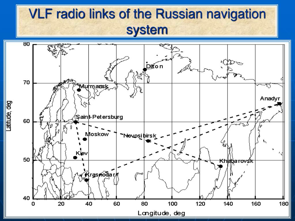
What the slide shows. The dashed lines are radio paths from Alpha transmitters to receiving sites, not new transmitter links: the deck's other slides name them Novosibirsk-Anadyr, Krasnodar-Anadyr, Krasnodar-St Petersburg, Novosibirsk-St Petersburg and Komsomolsk/Amur-St Petersburg (the transmitter being the first name, the receiver the second), plus Novosibirsk-Krasnodar and Novosibirsk-Khabarovsk in the diurnal-variation figure. The slide's own map labels the Far-Eastern station "Khabarovsk", which is the same station as El'ban. The researchers used the phase and amplitude of the navigation signals as a probe of the lower ionosphere during space-weather events. The deck's figure captions list the solar proton events of 29 to 30 September 1989 and 19 to 21 October 1989, a diurnal comparison during the superstorm of 28 October 2003, and a Krasnodar-St Petersburg phase variation at about 04:00 UTC on 26 April 1986, the time of the Chernobyl accident. The deck gives the working frequencies as 11.9 and 14.9 kHz. [DOCUMENTED description of what the deck says; the deck's Chernobyl-phase claim is [SINGLE-SOURCE] and I have not seen the underlying data]
Distances along those paths (great circle from the published coordinates, [ESTIMATE]): Krasnodar to St Petersburg about 1,700 km, Novosibirsk to St Petersburg about 3,150 km, Novosibirsk to Anadyr about 4,750 km, Krasnodar to Anadyr about 7,270 km. These are the "long baselines" at which VLF phase stays usable.
Signals that leave the Earth. The VLF energy does not all stay in the guide. Some leaks upward and travels along magnetic field lines through the plasmasphere as a "whistler-mode" wave, crossing to the opposite hemisphere and back. In January to March 2016 the Van Allen Probes satellites recorded Alpha pulses and used them as a probe of plasmaspheric electron density, finding the inversion matched independent in-situ measurements. They also detected echoes reflected from the opposite hemisphere along the same field line. [DOCUMENTED, Journal of Geophysical Research: Space Physics 2018]
RANGE, COVERAGE AND ACCURACY
The official numbers. Russian Wikipedia, quoting the institute history, gives 10,000 km range from the master station and an accuracy of 2.5 to 7 km, then adds that by 1999 the system had been "modernised" to about 1.2 to 1.5 km on 70% of the Earth's surface. The English Wikipedia article repeats 10,000 km and 2.5 to 7 km (2 to 4 miles). Another passage on Ruwiki gives "no worse than 2 nautical miles, up to 7 nautical miles at high latitudes". [SINGLE-SOURCE, conflicting; see SOURCE CONFLICTS]
What the physics allows. Omega's published accuracy was 4 nautical miles (about 7.4 km) with a practical 2 to 5 km under good conditions, using the same kind of signals, and the English Wikipedia article gives a precision of 2.2 km for the later Omega with differential corrections. Alpha uses nearly the same band and method, so it cannot do fundamentally better than Omega unless it applies better propagation models, more stations or differential corrections. The 1.2 to 1.5 km figure after 1999 is plausible as a statistical number on the modelled part of the globe but is a claim, not a measurement. [DOCUMENTED for Omega; [ESTIMATE] for the Alpha comparison]
Error budget, as I would expect it. [ESTIMATE, not a documented Alpha budget]
Coverage. Because the stations form a line across Eurasia (Krasnodar 38 E, Novosibirsk 84 E, El'ban 137 E), the geometry is good across northern Eurasia and the Arctic and poor along the line of the stations, where hyperbolas run nearly parallel. The Jacobsen note is that the original three stations lay almost on a west-to-east line across the continent, so the system was "obviously not intended for Soviet domestic use". He suggests it was originally intended for submarines and aviation in polar and North American regions and maybe the Indian Ocean. [DOCUMENTED geometry; the intended-use point is Jacobsen's inference]
Why three stations were fragile. With only three stations, if one is off the air the other two give just one hyperbola, which is not a fix. Jacobsen says that, with three stations, one outage left the other two "virtually useless for navigation". The 1991 announcement of Revda and Seyda was a response. [DOCUMENTED]
THE STATIONS
This table is the best consensus of the sources. Coordinates are as published, and differ in the last seconds of arc between sources.
Distances between the three working stations (great circle, [ESTIMATE] from the coordinates): Novosibirsk to Krasnodar about 3,390 km, Novosibirsk to El'ban about 3,470 km, Krasnodar to El'ban about 6,820 km. Those are long baselines, which suits a VLF phase system, since the lane width on the baseline is half a wavelength regardless of baseline length.
Master station. Jacobsen says the Novosibirsk transmitter "was (and still is) the master station" in his 2000 text. That makes the Novosibirsk phase the reference that the others are phased to, and the reason the phase steps at 21:00 UTC are seen at every station together. [SINGLE-SOURCE]
Transmitter site photos. Ruwiki lists a "photo" link for Novosibirsk from the panoramio website showing the masts, and Jacobsen has satellite views of the El'ban and Revda sites. I could not retrieve a stable copy of any, so there is no photograph of an Alpha transmitter on this page. [UNVERIFIED availability]
TRANSMITTERS AND ANTENNAS
What is public. Very little. English Wikipedia says the masts "must be very tall, for technical reasons. Unfortunately, no data are available for their height", and Ruwiki repeats the same sentence. A forum post (airforce.ru, copied to vif2ne.su) quoting what looks like an official list of Russian nav-system builds says that in 1968 RSDN-20 "Marshrut" was built as "3 stations with 6 antenna-mast structures of 273 m height". The same list gives the Chayka/Tropik build heights of 250 m, 360 m, and 460 m and 250 m. If that quote is right, the original system had two mast structures per station. I could not trace the list to a primary document. [SINGLE-SOURCE / UNVERIFIED]
Why the antenna is a problem. An 11.9 kHz wave is 25 km long. A 273 m mast is 0.011 wavelength, about 1% of a wavelength. A short vertical antenna radiates in proportion to the square of its height measured in wavelengths. For an idealised top-loaded mast with a uniform current, the radiation resistance is about 1,580 x (h / wavelength)^2 ohms, which comes to about 0.2 ohm for 273 m at 11.9 kHz, and about a quarter of that for the more realistic triangular current distribution. The ground system and loading coil add resistance of the order of an ohm or more. The efficiency is the ratio of radiation resistance to total resistance, so a few per cent up to perhaps 20 per cent is the realistic range, and a 500 kW input becomes tens of kW radiated. [ESTIMATE; standard short-antenna formulas]
That is why VLF antennas are enormous: Goliath and Cutler use huge top-loading "umbrella" and "flat-top" wire structures and very large ground systems, and a typical efficiency of tens of per cent is considered good. The Goliath VLF article gives about 10 per cent efficiency for the German station's design discussion and about 50 per cent total efficiency for Goliath's complete antenna system at 15 kHz as a design figure. See also Cutler / Jim Creek for the American practice. [DOCUMENTED, from those wiki pages]
Likely configuration. Omega stations, which Alpha is modelled on, used either a grounded or insulated guyed mast with an umbrella of wires, or a wire span across a valley or fjord. Omega's masts were 365 to 455 m tall (La Moure 365 m, Réunion 428 m, Liberia 417 m, Tsushima 389 m by one count) and the Tsushima mast was a tubular steel mast insulated from ground. An Alpha station with a top-loading umbrella of wires on a mast near 273 m, tuned with a large inductor (a helix in a pavilion at the base, placed between the antenna and ground to cancel the capacitive reactance of a short antenna), is the natural reading of the 273 m figure. [DOCUMENTED for Omega; the Alpha configuration is [SPECULATION] from that figure and the Omega design]
What a helix is. A short antenna looks like a capacitor from the feed point. To make it resonant at 11.9 kHz you add a large inductance in series. A VLF helix or loading coil is that inductor, made of heavy conductor in a large building at the foot of the mast, with a variometer (adjustable coupled coil) for fine tuning, because changing frequency during a frame, between 11.9, 12.65 and 14.88 kHz, means changing the tuning every 600 ms. Omega stations used an arrangement of switched tuning elements to hop between frequencies in the sequence. Whether Alpha stations do the same is not documented; given three carriers in sequence they must retune somehow. [DOCUMENTED for the principle; the Alpha tuning method is [UNVERIFIED]]
Transmitter power. The 1968 ITU frequency list reportedly gives 500 kW at the antenna on each frequency, as told by Jacobsen. That is a statement of the antenna input power in an international filing and not a measurement of radiated power. By the efficiency range above, radiated power would be tens of kilowatts. Omega is generally described as radiating about 10 kW per station. [SINGLE-SOURCE for 500 kW; the radiated figure is an [ESTIMATE]]
Ground system. All VLF stations rely on huge buried ground systems, radial wires many hundreds of metres long. Nothing public on the Alpha ground systems. [UNVERIFIED]
Running cost. Jacobsen notes that the eight Omega stations cost about 12 million US dollars a year, and mentions an unconfirmed rumour of closure for unpaid electricity bills in the 1990s. [SINGLE-SOURCE; rumour flagged as such by the source]
THE ANTENNA PHOTO ON THIS PAGE: WHAT IT IS AND WHAT IT IS NOT
Robert supplied a photograph labelled in Russian: four lattice masts numbered "мачта 3, 4, 5, 6", a "фидер" (feeder), and a low building labelled "павильон геликса" (helix pavilion), with an inset line drawing of a long antenna with cross-wires, labelled "С" (north) and "Ю" (south), and small labels I cannot read reliably. The watermark reads janto.ru. The question was whether this is the Russian Navy's Antey station at Vileyka, or a station comparable to Cutler.
I traced the image. It is figure H.1 of the janto.ru VLF-stations repository, annex H ("Other US VLF stations"), captioned there "Panorama and antenna diagram of the VLF radio station Balboa / Summit (mid-1960s)", with the illustrations credited to www.navy-radio.com. Balboa / Summit was the US Navy station NBA in the Panama Canal Zone, which janto.ru says used a Marconi triatic antenna: a vertical feeder shortened by an inductance at the base and a top-loading wire flat-top of six pairs of wires hung on cables stretched between three pairs of free-standing masts of 600 ft (about 183 m). That matches what the photo shows (several separate lattice masts, a feeder, a helix building) and the inset drawing (a long flat-top slung between mast pairs). [SINGLE-SOURCE; the identification rests on janto.ru's own figure caption, which I found by matching the image file to its page. I could not find a second independent confirmation]
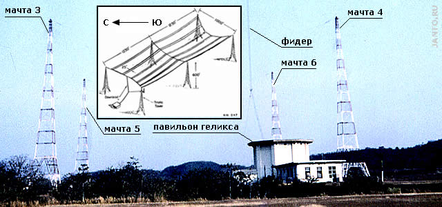
So the photo is not Antey, not Alpha, and not Cutler. It is an older American triatic design. It is still useful on this page because it shows, on a smaller scale and with Russian labels, the same parts every VLF station has: tall masts to hold the wire flat-top, a feeder from the antenna to the base, and a helix pavilion holding the loading inductance. It should not be read as a picture of any Alpha transmitter, whose masts and layout are not publicly photographed in anything I could reach. The Russian labels were added by janto.ru, whose VLF-antenna study uses the same vocabulary for every station it describes. [DOCUMENTED description of what the image shows; identification [SINGLE-SOURCE]]
HISTORY
WHY THE SOVIET UNION BUILT IT
The Soviet Navy and aviation needed global-range navigation without satellites in the 1960s. The United States built Omega for its ballistic-missile submarines and aircraft, alongside the TRANSIT satellite system. The USSR followed a parallel path: the satellite-Doppler Tsikada (civil) and Parus (military) systems from the mid-1970s, then GLONASS, whose first satellite flew in 1982 and which became fully operational in 1995 and then again by the 2010s. [DOCUMENTED, general background; I did not re-check the Tsikada / Parus dates for this page and treat them as [UNVERIFIED] in detail] See GLONASS for the modern system.
Alpha fills a different niche from Tsikada and GLONASS. It works continuously (a Doppler satellite fix waits for a satellite to pass), it works anywhere in the guide including at sea and in polar regions, and, because VLF penetrates sea water a little, a submarine can receive it near the surface. The ruwiki description says directly that the system was intended for "aircraft, ships and submarines (in the submerged position)". The word "submerged" needs care. The skin depth of sea water at 12 kHz is about 2 m (503 x square root of resistivity 0.2 ohm-m / 12,000 Hz), so the signal is attenuated by about 4 dB per metre, and a submarine can receive it only within a few to a dozen metres of the surface, or with a floating wire or buoy antenna. [ESTIMATE; standard skin-depth formula; seawater resistivity taken as 0.2 ohm-m]
Role in the Soviet toolkit. Alpha was the absolute position reset for inertial navigation. An INS drifts steadily, kilometres per day for the older ones, and a coarse but unlimited-duration fix every few hours bounds that drift. Alpha's kilometre-class accuracy is exactly matched to that job. [SPECULATION as to the specific doctrinal role; the technique is DOCUMENTED for Omega and the US Navy]
Aviation. A set of airborne equipment, the A-723 "Kvitok" (Квиток), was put into series production. Ruwiki says it was installed on the Tu-154 "and a whole range of other types of aircraft and helicopters, with somewhat different fit depending on the aircraft's navigation equipment". The Tu-154M operations manual (section 110, "Navigation radio equipment", item 110.20.00) is the cited source. [DOCUMENTED, via Ruwiki; I have not seen the manual]
RECEIVERS
Why a 4 m whip works at 12 kHz: a short antenna is a poor but usable receiving antenna at VLF because atmospheric noise, not receiver noise, is the limit. A short whip with an amplifier gives a flat, weak but stable voltage proportional to the field, which is exactly what a phase measurement needs. [DOCUMENTED principle]
TIMING STANDARDS
Everything depends on the clock. For differences of the phases of two stations to mean distance differences, the carriers of the two stations must be phase-locked to a common time standard to a small fraction of a cycle (a few microseconds at most, and in practice hundreds of nanoseconds). At 11.9 kHz one microsecond of clock error is 0.012 cycle, 4.3 degrees, or roughly 300 m of path. [ESTIMATE]
The documented clues that Alpha's clocks are derived from a single 1 MHz standard are the exact frequency relationships (F0 = 1 MHz / 1344) and the 25.2 s phase cycle, and the fact that the signal phase is reset daily at 21:00 UTC. The sources say that the project belonged to the institute of time (Ruwiki quotes "Институт времени") and that the same institute made frequency standards and on-board synchronisers for Soviet space systems. The RIRT history that Cyberleninka reproduces lists synchronisers for the Meteor weather satellites and the Salyut and Mir stations alongside the navigation work. What caesium or hydrogen clocks run at the stations, and how they are tied between Novosibirsk, Krasnodar and El'ban, is not public. Omega tied its stations together with caesium clocks and had the US Naval Observatory and the Coast Guard monitor the phase of each station against UTC; whether Russia monitors Alpha the same way is unknown. [DOCUMENTED for the institute's other work; the station-clock arrangement is [UNVERIFIED]]
Leap seconds. The 2018 Van Allen Probes paper found that the sequence loses synchronisation with UTC at a leap second and recovers a couple of days later. That points to a manual or delayed adjustment. [SINGLE-SOURCE]
COMPARISON: ALPHA, OMEGA, CHAYKA, GLONASS
The difference in one table's worth of words. Chayka is regional and accurate, Alpha is global-scale and coarse, GLONASS is global and precise but weak. They answer different failures: Chayka covers local GNSS jamming, Alpha covers a large-scale loss of satellites or local jamming that spares the VLF band.
WHY IT HAS BEEN KEPT RUNNING
Russian navigation planning documents, discussed in the Chayka article, put the emphasis on GLONASS plus inertial plus a ground-based backup, with Chayka (and eChayka plans) in the backup role. I found no official document describing Alpha's future role in 2026. Some commentary says "Russia's emphasis on redundant, jam-resistant positioning". That phrase is a commentator's, not an official statement. [UNVERIFIED]
Vulnerability. There are three working transmitters, each a conspicuous site. Whether they are hardened, and how well, is not public. A system with three stations that cannot produce a fix with one of them off the air is fragile, and the Western Omega lost to GPS partly for cost rather than fragility. [SPECULATION as to the planning assumptions]
IS IT "THE WORLD'S ONLY ACTIVE VLF NAVIGATION SYSTEM"?
Robert quoted a line saying that Alpha "is the world's only active VLF-based long-range navigation system". I checked what can be checked.
The sentence that Robert pasted also says the system underlines "Russia's emphasis on redundant, jam-resistant positioning technologies for strategic and operational needs". As noted above, that is interpretation. It may well be correct, but I found no Russian official statement that says so. [UNVERIFIED]
STATUS IN 2026
What is documented.
What I cannot say. I cannot say from the sources whether all three stations are on the air as of 18 October 2026, which of the three are working, whether the system is still used by the Navy or aviation, or whether any station has been rebuilt. "Operating, intermittently" is the supportable statement. [UNVERIFIED for anything more specific]
How to check yourself. Tune a VLF receiver (a soundcard with a short whip and amplifier will do) to 11.905, 12.649 and 14.881 kHz. You are looking for 400 ms bursts every 600 ms in a repeating 3.6 s pattern. The signals are strongest in northern Europe in the evening. [DOCUMENTED]
ALPHA IS NOT ANTEY: THE VLF COMMUNICATIONS STATIONS
There is a second set of Russian VLF transmitters that gets confused with Alpha because it is also very low frequency, also huge, and also Russian. These are the communications stations that send messages to submarines. The best known is the Russian Navy's Antey (Антей) station near Vileyka in Belarus (callsign RJH69, the 43rd communications centre of the Navy). Antey, and the older rebuilt Goliath near Nizhny Novgorod, carry coded messages to submarines. They are not part of Alpha and carry no navigation fixes. The difference matters:
A separate article on Antey is being written for this database: Antey / Vileyka VLF. For the existing pages on the other stations see Goliath VLF and Cutler / Jim Creek; for the wider communications background see Russian C3 and HFGCS network. The Soviet and Russian VLF communications stations are catalogued in a janto.ru study (annex N). [DOCUMENTED]
SOURCE CONFLICTS
WHAT WOULD SETTLE THE OPEN QUESTIONS
SUGGESTED SUB-ARTICLES
RELATED ARTICLES
SOURCES
Own working: wavelengths, difference-frequency lanes, baseline distances, short-antenna radiation resistance and efficiency, skin depth and the receive-clock sensitivity are arithmetic from published frequencies and coordinates and are marked as estimates.
IN ONE SENTENCE
Alpha (RSDN-20) is Russia's very-low-frequency phase-comparison navigation system, the Soviet counterpart of the Omega system that closed in 1997: three transmitters at Novosibirsk, Krasnodar and El'ban send 400 ms bursts on 11.9, 12.65 and 14.88 kHz in a 3.6-second frame, giving kilometre-class fixes over thousands of kilometres without satellites; it works intermittently, is largely undocumented as to its masts and clocks, and is a different thing from the Chayka pulse system and from the Antey submarine-communication station.