WHAT IT IS
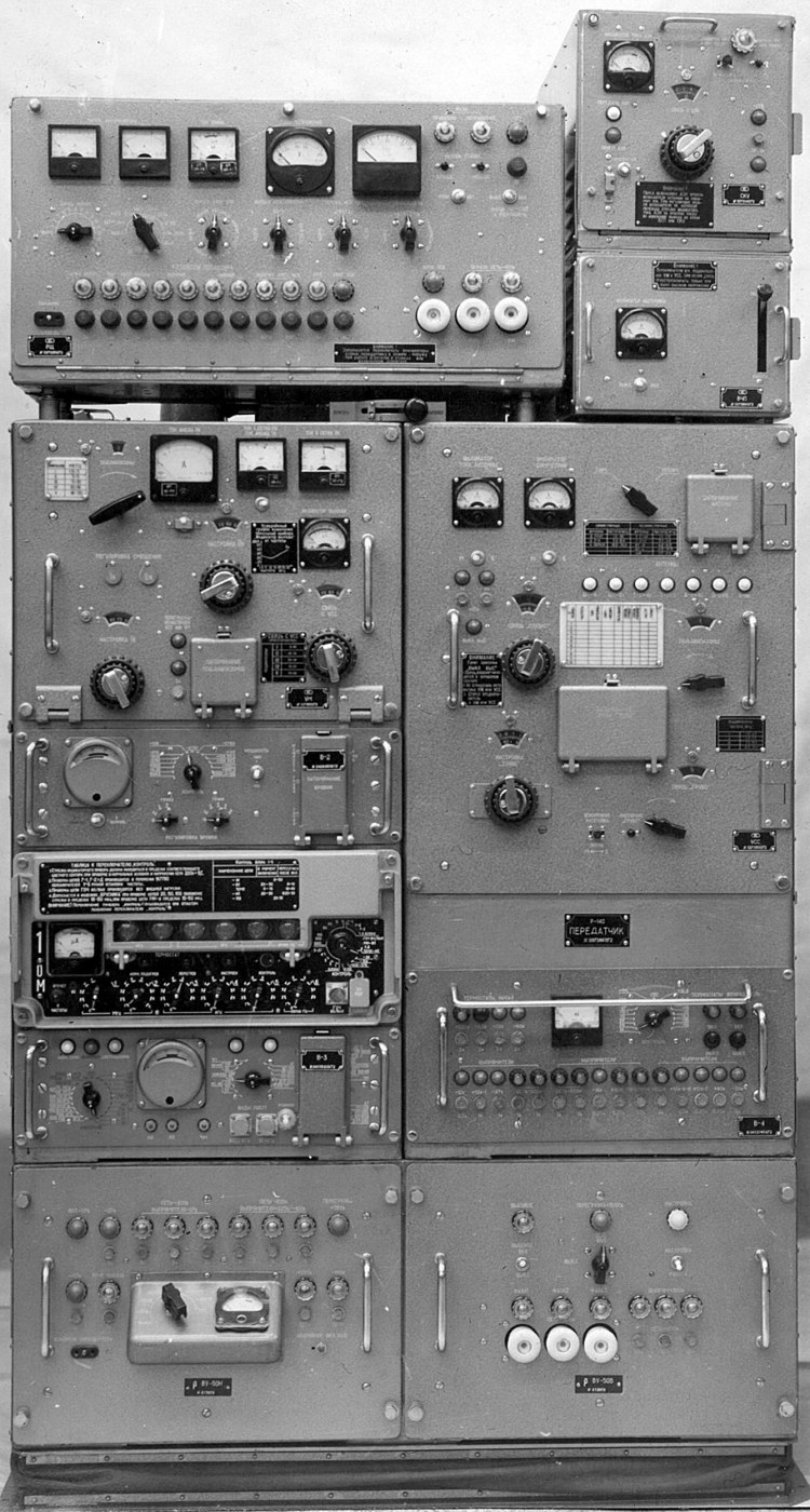
The R-140 (Р-140) is a Soviet mobile single-sideband high-frequency radio station of the one-kilowatt class, built into a truck shelter and meant to carry long-haul voice, Morse and teleprinter traffic between front, army and service-branch headquarters. The declassified technical description calls it an "automobile single-sideband one-kilowatt radio station" (автомобильная однополосная однокиловаттная радиостанция) for short-wave communication "in front and army nets of the ground forces, rocket forces, national air defence forces and air force." That one sentence sets the scale. This is not a tactical backpack set or a tank radio. It is an operational-level station: the kind of set a front or army headquarters, a missile formation or an air-defence corps used to reach peers and subordinates hundreds to a couple of thousand kilometres away. [DOCUMENTED]
The station covers 1.5 to 29.9999 MHz on a discrete grid with 100 Hz steps, puts out 800 to 1000 W in single-channel SSB or telegraph, and can be retuned automatically to any of ten prepared frequencies in 30 to 40 seconds. The transmitter, a separate receiver (the R-155P), a radio-relay half-set for remote control, teleprinter, telephone switching, generators and an entire antenna field all ride in one high-mobility truck. A remote-control trailer could be parked up to 10 km away so the operators were not sitting next to a kilowatt HF emitter that an enemy direction-finding net could locate. [DOCUMENTED]
The surviving open record of the R-140 comes almost entirely from the declassified manual set. Those documents were downgraded by USSR Ministry of Defence order No. 0105 of 15 May 1985 and later scanned and summarised by the radioscanner.ru "Museum of Non-Consumer Electronics" (Музей небытовой электроники) run from Riga. Almost every hard number in this article traces to those books, chiefly the technical description ЯР1.201.013 ТО/С, Book 1, edition 1-68, and the R-140M technical description ЯР1.600.004 ТО of 1982. Where we go beyond those books we say so. [DOCUMENTED]
This article concentrates on how the station works: how the exciter builds a frequency and a single-sideband signal, how the power amplifier gets that signal up to a kilowatt, how the automatic matching unit with its motor-driven rotary inductors finds a match into everything from a 10 m whip to an 80 m sloping dipole, and how the whole station is fed, cooled, deployed and controlled. History, variants, surplus use and comparison with Western and later Soviet sets follow.
SOURCE LABELS USED HERE
[DOCUMENTED] means the statement is taken from the declassified R-140 / R-140M manuals as quoted by the museum pages, or from equally hard primary material. [SINGLE-SOURCE] means one reasonably credible source only. [UNVERIFIED] means it circulates but we could not tie it to a primary document. [ESTIMATE] means our own engineering number derived from documented values. [SPECULATION] means reasoned opinion. [BACKGROUND] means general radio or historical knowledge that is not specific to the R-140 but is needed to explain it.
WHERE IT SITS IN THE SOVIET HF FAMILY
The manual itself names its predecessors. It says the technical description was written for officers and radio specialists "who know the fundamentals of radio engineering and have experience operating military radio stations of the same purpose (R-102M2 and R-113M3)." It goes on to say the R-140 gives "more stable and reliable radio exchange compared with radio stations of the old fleet" thanks to a wide frequency range, a large number of working frequencies, a high degree of automation and jam-resistant modes, "first of all single-sideband radiotelephony." [DOCUMENTED]
That is the key to understanding the set. The older Soviet operational-level HF stations were AM and Morse machines with hand-tuned valve transmitters and free-running or crystal-switched oscillators. The R-140 generation brought three things at once: SSB as the primary voice mode, a synthesised frequency grid with crystal-reference stability, and motorised automatic retuning of the high-power stages. The manual stresses "fundamentally new, more complex circuits and designs with wide use of semiconductor devices and printed circuits." In practice the low-level exciter and control logic are transistorised while the power chain stays with valves. [DOCUMENTED]
The R-140 was designed to talk to "same-type and other single-sideband radio stations, to radio stations of the old fleet, and also to aircraft single-sideband radio stations in identical modes and on common parts of the band." That requirement drives several unusual features, especially the selectable carrier level, which we explain below. [DOCUMENTED]
THE STATION AT A GLANCE
Frequency range: 1.5–30 MHz (1.5–29.9999 MHz). Grid: discrete, 100 Hz steps. Frequency setting: decade method, read directly on a digital display or from the positions of the knobs on device 1-0M. Ten pre-set "fixed waves" for both transmitter and receiver, each remembering exciter output level, mode, antenna type and other settings. Automatic retune between any two of the ten prepared waves: 30–40 seconds. [DOCUMENTED]
Stability: high-stability quartz reference oscillators, relative drift not more than ±2×10⁻⁷ over six months, with provision to correct against time-signal stations; setting accuracy 1×10⁻⁸. Total transmitter frequency error in frequency-shift telegraphy not more than ±15 Hz in FSK-125, ±24 Hz in FSK-250 and ±32 Hz in FSK-500 and dual-channel DFSK-250. FM mode: ±3 kHz. [DOCUMENTED]
Power: 800–1000 W in telegraph or single-channel SSB telephone with 3 % carrier and a single-tone test signal. Output can be reduced in discrete steps of 50–100 W from nominal down to 50 W by setting the exciter output level. [DOCUMENTED]
Range with same-type stations on frequencies chosen from ionospheric data: aural telegraphy up to 2000 km; teleprinter or single-channel SSB telephone at the halt 1000–1500 km; on the move with the near-vertical-incidence antenna up to 300 km; on the move with a whip about 70 km. With aircraft SSB stations and diversity reception, 2500 km. Two-channel SSB working shortens range noticeably because total power is shared between channels. [DOCUMENTED]
Readiness: 20 minutes after switch-on only 70 %-carrier telephone and aural Morse are available; all other modes after one hour of warm-up. Full deployment by a trained four-man crew in summer: 2 hours 30 minutes, using a site of 150 × 100 m. Erecting the NVIS whips for working on the move: 5–10 minutes. [DOCUMENTED]
Supply: three-phase mains 220 or 380 V, an AB-4-T/230 petrol-electric set, or a power take-off from the truck engine (reserve). Consumption not more than 5 kW from the mains and 4 kW from the generator or PTO. [DOCUMENTED]
Crew: four — station chief, senior radio-telegraphist, radio-telegraphist and driver-electrician. The R-140D adds two more radio-telegraphists for the remote trailer. [DOCUMENTED]
STATION COMPOSITION
The R-140 manual lists the station contents in order. The radio transmitting device with its set of transmitting antennas; the R-155P receiving device with a receive-antenna switch; antenna-feeder devices; the distribution board RShch; a half-set of the R-405P-T1 radio-relay station; the station control panel PUR with a remote-control/telesignalling unit; an R-311 receiver; an R-105M VHF radio; a driver's-cab panel; an STA-M67B teleprinter; a TA-57 field telephone; an ATGS-P telephone and loudspeaker intercom; a line input; a power input; an automatic mains switch and protection unit; a voltage stabiliser; AB-4 and AB-1 petrol-electric sets; and the engine power take-off. [DOCUMENTED]
That list explains the station's personality. The transmitter and the R-155P are the heart. The R-311 is a simple, battery-powered general-coverage valve receiver kept as a standby listening set; it runs from a 2KN-24 battery so it still works if the main supply is down. The R-105M is a man-portable VHF FM set (the classic 1950s–60s platoon/company radio) that lets the truck talk on local VHF nets, especially from the driver's cab while on the move. The R-405P-T1 relay half-set is a line-of-sight radio link that carries the remote-control and traffic channels to the trailer or to a signals centre. The STA-M67B is the standard Soviet start-stop teleprinter of the period. [DOCUMENTED] / [BACKGROUND]
The R-140D variant is the R-140 plus a special trailer, the remote control post VPU (вынесенный пункт управления). The VPU equipment sits in a KUNG-2 box on a single-axle 1-P-3S trailer. It contains the VPU control desk with switching block, a telecontrol/telesignalling dispatcher device and rectifier, a full R-405P-T1 relay set with adapter box, a line input, antenna gear, a power board and an AB-1 petrol-electric set. The VPU draws not more than 1 kW from the AB-1-O/230 or a single-phase 220 V line. [DOCUMENTED]
VEHICLES AND SHELTERS
The original R-140 / R-140D operating compartment is a K66U1-DP body on a ZiL-157KEG high-mobility truck, or on a ZiL-131. The "KEG" suffix on ZiL chassis indicates a screened (shielded) electrical system for radio vehicles. [DOCUMENTED] / [BACKGROUND]
The body is laid out as an operating room with the transmitter rack, receiver, PUR and teleprinter, plus a separate rear compartment for the AB-1 generator where batteries are also charged. The museum shows the control panel for an O-30 heater and the heater in its compartment; a petrol heater of that type kept the shelter usable in winter, because the equipment was rated for a shelter temperature of minus 10 °C to plus 50 °C. [DOCUMENTED]
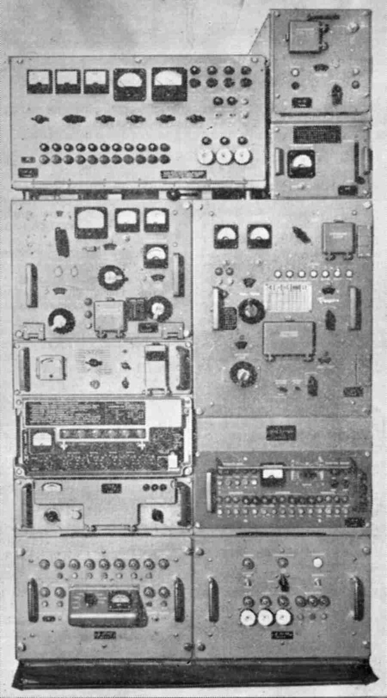
The later R-140M kept the same idea on newer chassis. In surviving photographs and sale listings R-140M stations appear on ZiL-131 and later on KamAZ-4310 with a box body, and some service-branch sets are described on Ural-375/4320 chassis. We could not find a manual page that fixes the KamAZ body designation, so treat the specific chassis-to-variant pairings as [SINGLE-SOURCE] at best. What is firm is that the M-model electronics fit the same basic rack format, as the museum's photographs of the two transmitter racks show. [UNVERIFIED]
VARIANTS
R-140. Base station, exciter VO-64, ZiL-157KEG or ZiL-131, manual set ЯР1.201.013, first editions 1968. The spectral passport is dated 1967, so the design was complete and measured by then. [DOCUMENTED]
R-140D. R-140 plus the remote control trailer VPU with R-405P-T1 relay, controllable from up to 10 km. [DOCUMENTED]
R-140M. Modernised station, technical description ЯР1.600.004 ТО of 1982. The museum lists its exciter as VO-71B made up of devices 1-0V, V-2, V-3 and V-4, while the original R-140 used VO-64 with device 1-0M in place of 1-0V. The power amplifier and matching unit kept the same function and the same rack slots. [DOCUMENTED]
R-140M-1. Technical description ЯР1.600.013 ТО, dated 1977 in the museum list. That earlier date than the 1982 R-140M book suggests documents were reissued and that numbering does not track chronology neatly. [DOCUMENTED] for the document; the reason is [SPECULATION].
"Береза" (Bereza, "Birch"). Not an R-140 variant by name, but a station whose transmitting device is built from the same blocks: a VO-71 exciter rack, a transmitter rack holding UM, USS, RShch and VU-50, and a base frame with stabiliser, ABV-2 switch, load, RF switch and spares boxes. Its power amplifier ЯР2.068.127 and matching unit ЯР2.240.043 differ only slightly from the R-140 blocks. Its manual is ЯР1.600.020, 1977 and 1982 editions. [DOCUMENTED]
R-140-0.5 and other low-power derivatives. A 500 W member called R-140-0.5 (Р-140-0,5) is widely named on collector and ham forums, usually as a lighter derivative using the same exciter generation. We could not find its technical description in the declassified set the museum holds, so its chassis, date and exact power stage are [UNVERIFIED]. [UNVERIFIED]
Foreign production. The museum shows a power amplifier "made in the GDR", photographed by a French amateur. That supports licensed or cooperative production of R-140 blocks in East Germany for Warsaw Pact use. [DOCUMENTED] that such a block exists; the scale of production is [UNVERIFIED].
THE TRANSMITTING DEVICE: WHAT EACH BLOCK DOES
The manual gives the transmitting device five jobs: form the grid of working frequencies; form the single-sideband signal and all other kinds of emission; suppress spurious conversion products; amplify to the required power; and match the amplifier output impedance to the antennas. Each job maps onto a physical block in the rack. [DOCUMENTED]
Exciter VO-64 (R-140) or VO-71B (R-140M). Four devices. 1-0M (or 1-0V) stabilises, sets and monitors the exciter frequency. V-2 forms the station's output frequency range and amplifies the exciter output to the level needed to drive the PA. V-3 forms every kind of telephone and telegraph emission, and sets and stores them for automatic recall. V-4 supplies DC and AC power to the exciter. [DOCUMENTED]
Power amplifier UM (усилитель мощности) ЯР2.068.071. Two valve stages, at least 1000 W across 1.5–30 MHz in all modes. [DOCUMENTED]
Matching-balancing unit USS (устройство согласующе-симметрирующее) ЯР2.240.001. Transforms the input impedance of any transmitting antenna, balanced or unbalanced, into a 50 Ω resistance; couples the unbalanced amplifier output to balanced antennas; filters harmonics. [DOCUMENTED]
Matching-switching unit SKU. Connects and roughly matches the near-vertical-incidence antenna (AZI), and switches the AZI and the 10 m whip between transmit and receive for simplex working. [DOCUMENTED]
RF switch VChP. In the TUNE position it puts the PA output into a 50 Ω dummy load and connects the USS input to one arm of a bridge with a meter, so both can be tuned separately "without going on air." In WORK it connects PA to USS. [DOCUMENTED]
Rectifier VU-50. Feeds the PA valves and the automatic retuning system. [DOCUMENTED]
Control of the transmitter's emissions is through the PUR. Information signals enter the exciter, modulate or key the RF it generates, and the modulated signal from the exciter's output device goes to the PA and on through the matching devices to the antenna. [DOCUMENTED]
HOW THE EXCITER MAKES A FREQUENCY
The manual summary is short: a discrete grid at 100 Hz intervals over the whole range, set by the decade method, referenced to high-stability crystal oscillators. To understand what that meant in the mid-1960s it helps to walk through how such an exciter is built. The detailed VO-64 schematic is in Albums 1 and 2 (ЯР1.201.013-Оп1 and -Оп2), which we have not reproduced, so the architecture below is a description of the documented behaviour plus the standard Soviet practice of the period. [BACKGROUND]
The reference. Everything starts from one quartz oscillator in a thermostat. The ±2×10⁻⁷ over six months figure is an oven-controlled crystal, not a bare crystal; a bare crystal in a truck shelter swinging from −10 to +50 °C would drift far more. The manual provides for correction against time-signal transmissions, which in the USSR meant stations such as RWM in Moscow broadcasting standard frequencies. An operator could beat the internal reference against a standard-frequency signal and trim it. The quoted setting accuracy of 1×10⁻⁸ is the resolution of that correction. [DOCUMENTED] for the figures; RWM as the usual reference is [BACKGROUND].
Why stability mattered so much. SSB voice with a suppressed carrier is only intelligible if the receiver's reinserted carrier is within roughly 20–50 Hz of the transmitter's. At 30 MHz a 2×10⁻⁷ error is 6 Hz; two stations each holding that tolerance are at worst 12 Hz apart, comfortably inside the window. That is why the manual can promise "two-way short-wave radio communication without searching and without retuning in all modes" between same-type stations. The operators dial the same number and the link works, which the old AM fleet could never guarantee. [ESTIMATE]
Decade synthesis. The "decade method" means each digit of the frequency — tens of megahertz, megahertz, hundreds of kilohertz, tens of kilohertz, kilohertz and hundreds of hertz — has its own switch, and each switch selects a fixed set of signals derived from the reference. Those signals are mixed and filtered in stages so the final output equals the sum of the selected decades. Soviet exciters of this period generally used a mix of direct synthesis (harmonic generators, dividers and filters selecting spectral lines of the reference) and phase- or frequency-locked interpolation oscillators for the finer decades. With 100 Hz steps from 1.5 to 29.9999 MHz there are 285,000 channels. The 1-0M device's knobs show the frequency mechanically and the digital board displays it. [DOCUMENTED] for decade setting and the readout; internal topology is [BACKGROUND].
Spur suppression. One of the transmitter's five official tasks is "suppression of side products of conversion." A mixing synthesiser makes many unwanted products; each must be filtered before amplification, or the kilowatt PA will radiate them. That is part of why the V-2 device, which forms the output range, sits between the synthesiser and the PA, and why the PA itself is a tuned amplifier rather than a broadband one: its tuned circuits add selectivity at the final frequency. The 1967 spectral passport, listed in the museum's document set, would contain the measured spurious and harmonic levels. [DOCUMENTED] for the existence of the requirement and passport; mechanism is [BACKGROUND].
HOW THE EXCITER MAKES SSB AND THE OTHER MODES
Device V-3 is the "mode" device. It forms all telephone and telegraph emissions, and stores the settings for automatic recall with the ten fixed waves. [DOCUMENTED]
Single sideband. Single-sideband suppressed-carrier telephony removes the carrier and one sideband, putting all the power into one 300–3400 Hz voice channel. Compared with full AM it gives about 9 dB more useful talk power for the same peak transmitter power and halves the occupied bandwidth, which halves the noise the receiver lets in. For an army HF net that is the difference between a usable link and noise. Soviet exciters of this generation generated SSB at a fixed low intermediate frequency with an electromechanical or crystal filter, then translated it to the operating frequency by mixing with synthesiser outputs. [BACKGROUND]
Upper, lower and both sidebands. The station offers single-channel SSB on the upper or lower sideband, simplex or duplex; and two-channel SSB with one channel on the upper and a different channel on the lower sideband, in duplex. It also has a "Telephone Chord" (ТЛФ АККОРД) mode in which both channels carry the same audio at once, a kind of frequency diversity against selective fading. [DOCUMENTED]
Selectable carrier level. The most distinctive feature is the choice of carrier level: 3 %, 10 % or 70 %. The manual explains why. With same-type stations without automatic frequency control, no more than 3 % carrier is used: the R-140's stability means the receiver needs no pilot. With aircraft stations, 10–35 % carrier is sent so the aircraft receiver's automatic tuning can lock to it. With "old fleet" stations whose receivers are only built for double-sideband AM, 40–80 % carrier is sent so an ordinary AM detector can recover something intelligible. The 70 % mode is also the only telephone mode available 20 minutes after switch-on, because a large carrier tolerates the drift of a not-yet-stable oven. [DOCUMENTED]
Clipped SSB. A clipped upper-sideband mode raises average talk power by limiting peaks. [DOCUMENTED] Clipping costs some fidelity but adds several decibels of effective punch for weak-signal phone work. [BACKGROUND]
FM telephone. Single-channel FM telephone is included, with ±3 kHz absolute stability. On HF this is mostly a short-range or interoperability mode. [DOCUMENTED] / [BACKGROUND]
On-off Morse (AT). Hand-keyed amplitude telegraphy on the carrier, simplex and duplex. This is the mode with the 2000 km range figure, because a narrow 260 Hz receiver filter (the TLG-U position) recovers a signal a voice channel would bury. [DOCUMENTED]
Frequency-shift telegraphy (ChT). Shifts of 125, 250 and 500 Hz, keyed by hand or teleprinter, in sub-modes I, II and III. The museum lists maximum telegraph distortion as 9 % at 50 baud for FSK-125 and 7 % for FSK-250/500. [DOCUMENTED]
Dual FSK (DChT, ДЧТ). Two teleprinter channels on one carrier using four tones with 250 Hz shift: each combination of the two channels' marks and spaces selects one of the four frequencies. One channel may be teleprinter and the other hand Morse. With add-on high-speed equipment, DChT-250 carries synchronous 150 baud telegraphy. Distortion figures are 22 % for 150 baud synchronous and for 50 baud asynchronous. [DOCUMENTED] The four-frequency scheme is the standard meaning of DChT [BACKGROUND].
Retransmission. The station can relay one- and two-channel telephone and telegraph in duplex. A front headquarters could thus use one R-140 as a relay to extend a link. [DOCUMENTED]
Duplex spacing. For duplex the receiver and transmitter must be separated by at least ±240 kHz in the 1.5–12 MHz range, and by at least 2 % of the transmit frequency from 12 to 30 MHz. That spacing lets the R-155P receiver, fed from separate receiving antennas, survive a kilowatt transmitter a few metres away. [DOCUMENTED]
Audio quality. End-to-end nonlinear distortion of the link 5–8 %; frequency-response ripple across 300–3400 Hz not more than 7.5 dB; intelligible crosstalk from lower to upper sideband at least 50 dB down (48 dB the other way); unintelligible crosstalk 22 dB. [DOCUMENTED]
"Data". The R-140 has no modem in the modern sense. Its data capability is teleprinter FSK and DFSK, plus 150 baud synchronous with external equipment. Encryption was done outside the radio, in telegraph or telephone secrecy equipment on the line side; the R-140 itself is a clear-channel bearer. [DOCUMENTED] for the modes; external crypto as practice is [BACKGROUND].
HOW THE TEN FIXED WAVES WORK
A "fixed wave" (фиксированная волна) is a stored station configuration. The manual says the operating compartment can prepare ten fixed waves for the transmitter and ten for the receiver, remembering exciter output voltage, mode of work, antenna type "and other" parameters. Selecting one sets the synthesiser decades, the V-3 mode, the exciter drive level, and — the time-consuming part — drives every motorised tuning element in the PA and USS to its stored position. [DOCUMENTED]
How does a 1960s set "remember" ten positions of a rotary inductor? The PA description gives the clue: "all axes of the controls are connected to the axes of the reducers and memory blocks through flexible couplings." The memory blocks (блоки запоминания, БЗ / БМЗ) are electromechanical. The USS front panel also carries "two switching blocks for memorising antennas and positions of the switch COUPLING COARSE." In practice the operator tunes each wave by hand once, then the position of every shaft is captured, either by setting cams or code disks in the memory block or by plugs in the switching blocks. When the wave is called, a motor drives each shaft until a contact or code disc reports that the stored position has been reached. [DOCUMENTED] for the memory blocks and flexible couplings; the exact capture mechanism is [ESTIMATE].
That is why retuning takes 30 to 40 seconds rather than milliseconds: the slowest element is the long rotary inductor in the USS, which must travel along many turns. The manual's indicator lamp "HV OFF" in the USS confirms one more interlock: high voltage is removed while the automation moves, so contacts are never moved under RF load. [DOCUMENTED]
THE POWER AMPLIFIER
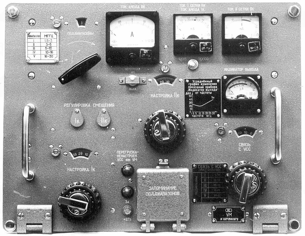
The power amplifier ЯР2.068.071 is one pull-out drawer in the transmitter rack. It takes the exciter's low-level output and raises it to not less than 1000 W across 1.5–30 MHz in all modes. The museum's system-level page gives the transmitter output as 850–1000 W, and the station-level specification gives 800–1000 W, so the "1 kW" label is the nominal PA rating and the delivered figure after the switching and matching losses is somewhat lower. [DOCUMENTED]
Two stages. The first stage is a voltage amplifier: a linear resonant amplifier in class A with two 6E5P valves in parallel, common cathode, series feed. The 6E5P (6Э5П) is a small high-transconductance noval pentode, a typical Soviet choice for wideband or driver service. Class A guarantees linearity at the cost of efficiency, which does not matter at driver level. Its job is to raise the exciter voltage to what the output valve's grid needs. [DOCUMENTED] / [BACKGROUND] for the valve characterisation.
The second stage is the power amplifier proper: one GU-43B (ГУ-43Б) high-power generator tetrode, common cathode, series feed, operating in class AB with a 90° anode current conduction half-angle and without control-grid current. "Without grid current" is the class AB1 condition. An AB1 tetrode needs only voltage drive, not power, at its grid; that is why a pair of small pentodes can drive a kilowatt stage. A 90° half-angle means the anode conducts for half of each RF cycle, the classic class B point, which gives good linearity for SSB with roughly 60–70 % plate efficiency. [DOCUMENTED] for the circuit; efficiency is [ESTIMATE].
The GU-43B, and the GU-78B / GU-84B correction. Several web pages and forum posts say the R-140 power amplifier uses a GU-78B, or even GU-84B valves. The declassified technical description quoted by the museum says plainly: one GU-43B tetrode. Nothing in the R-140, R-140M or Bereza material we read names a GU-78B or GU-84B. The confusion has a likely source. The GU-78B is a later, larger Soviet tetrode in the 2.5 kW anode-dissipation class, popular with amateurs, and the GU-84B is a still larger tetrode used in high-power naval and fixed transmitters such as the R-631 Plamya, which uses several of them. Both turn up in Russian ham amplifier lore alongside "R-140" parts. Unless a primary document for a specific R-140 sub-variant says otherwise, the correct statement is: R-140 and R-140M PA — one GU-43B, driven by two 6E5P. [DOCUMENTED] for GU-43B; the GU-78B/GU-84B attributions are [UNVERIFIED] and contradicted by the manual; the explanation of their origin is [SPECULATION].
About the GU-43B. The GU-43B is a ceramic-metal beam tetrode with a coaxial base, designed for forced-air cooling through an integral radiator, with anode dissipation of about 1 kW and use up to VHF. Hams commonly run it at 2.5–3 kV on the anode and 300–350 V on the screen. In the R-140 its high voltage comes from the VU-50 rectifier. We did not have the VU-50 page with its voltages, so anode and screen values in the station are [ESTIMATE] from the tube's typical ratings, not from the manual. [BACKGROUND] / [ESTIMATE]
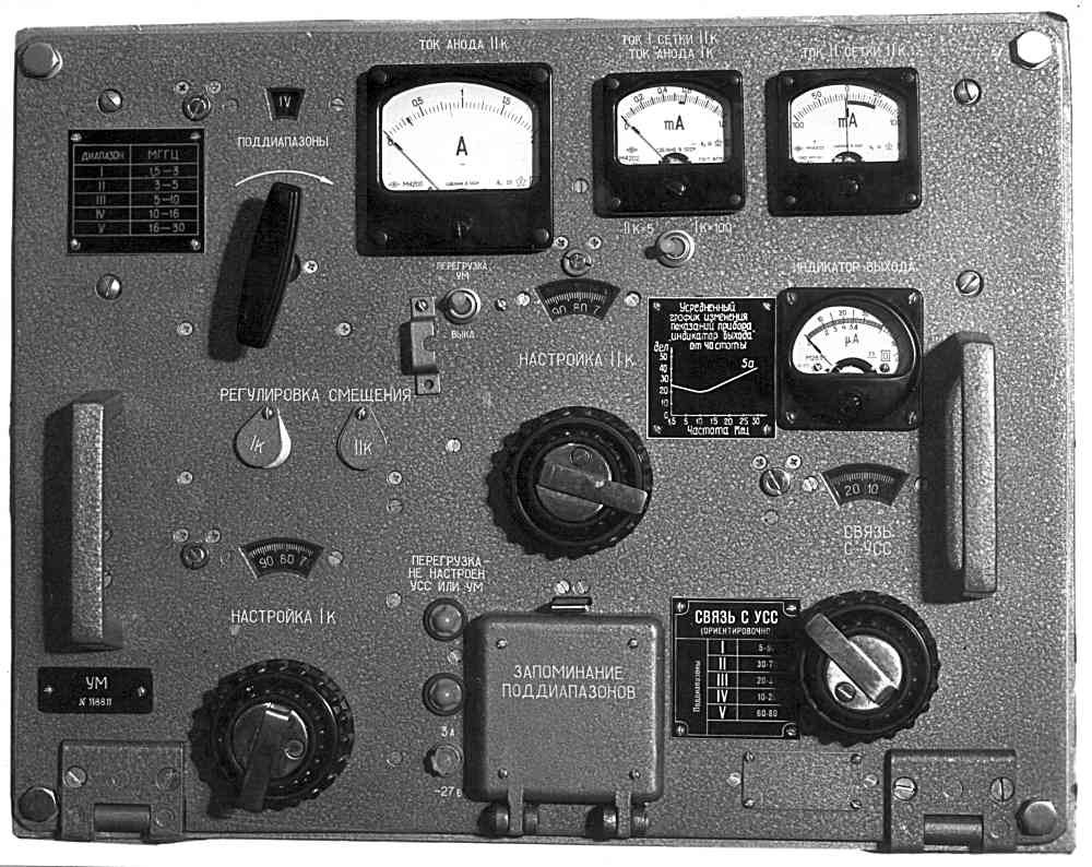
Five sub-bands. The PA's tuned circuits cover the HF range in five sub-bands: I 1.5–3.0 MHz, II 3.0–5.0, III 5.0–10, IV 10–16 and V 16–30 MHz. Each sub-band has its own tapping and capacitor arrangement on the band switches, while the variometers provide continuous tuning within the band. A ratio of 2:1 or less per sub-band is typical for a tank circuit that must keep reasonable loaded Q and harmonic rejection everywhere. [DOCUMENTED] / [BACKGROUND]
Variometers instead of variable capacitors. Both stages are tuned with variometers (вариометр) — variable inductors in which the inductance changes by rotating one coil inside another or by moving a contact — rather than with big air-variable capacitors. The second stage's output network uses a variometer plus a coupling capacitor and vacuum capacitors on special holders that "make replacement of the capacitors easy." Tuning by inductance keeps the high-voltage capacitors fixed, reliable and compact, and suits motor drive because a variometer can be rotated through a gear train with no end-stops in the middle. [DOCUMENTED] / [BACKGROUND]
Mechanical layout. Both stages sit in one pull-out block: a cast silumin (aluminium-silicon alloy) frame with a front panel that hinges down. A wall divides the frame. The front compartment holds the automatic retuning mechanisms; the rear holds the second stage. Two small special compartments low at the back hold the first-stage panel and the wiring of the second-stage valve socket. Four steel brackets with rollers slide in pockets under the frame. A travel limiter on the frame floor stops the block in the rack. [DOCUMENTED]
The first stage is built on its own aluminium panel. On top are the anode choke, two ceramic valve sockets and the sub-band switch; underneath, the variometer, a six-pin power connector, two RF connectors (in and out) and a screen separating grid leads from anode circuits. Screens close the compartment top and bottom. Separating the grid and anode circuits is what keeps a high-gain resonant stage from oscillating. [DOCUMENTED] / [BACKGROUND]
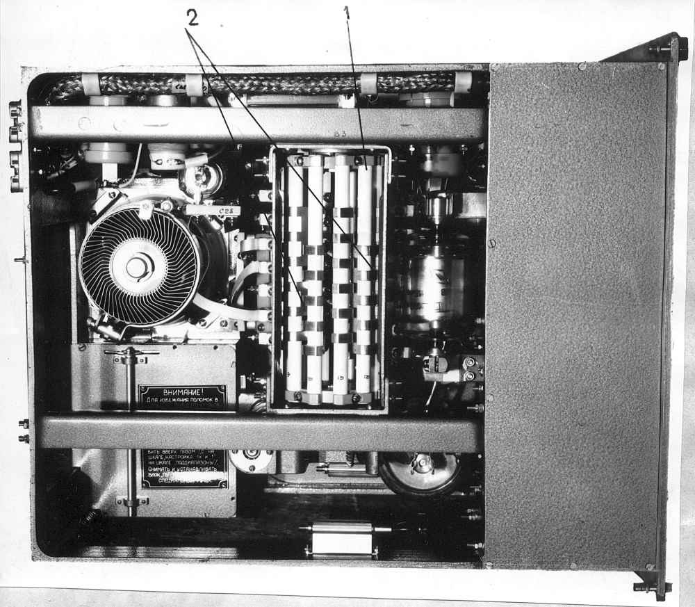
In the second-stage compartment, a variometer and coupling capacitor are mounted low down. Above the variometer on two angle brackets is the sub-band switch, whose shaft is geared to the first-stage band switch through bevel gears, so a single motor switches both stages together. On the middle wall are the vacuum capacitors. To the right are K15U-2 capacitors, two chokes and a current transformer, and on the right side a board of TVO resistors. On the back wall: two locator bushings, the RF output connector, a 17-pin PA power connector, a 22-pin automation connector and the RF input connector. [DOCUMENTED]
Front panel. Meters for anode and grid current of both stages and an output indicator, with a toggle switch to select the readings; a switching jack block; a fuse and a lamp that lights if it blows; a toggle enabling the overload protection for the PA and USS; and dial lights. Four control shafts come through the panel from the automatic mechanisms: sub-band switch, tuning of the first circuit, tuning of the second circuit, and coupling to the USS. Overall size with projections 344 × 446 × 549 mm; mass 34 kg. The Bereza PA ЯР2.068.127 is the same size and 32 kg. [DOCUMENTED]
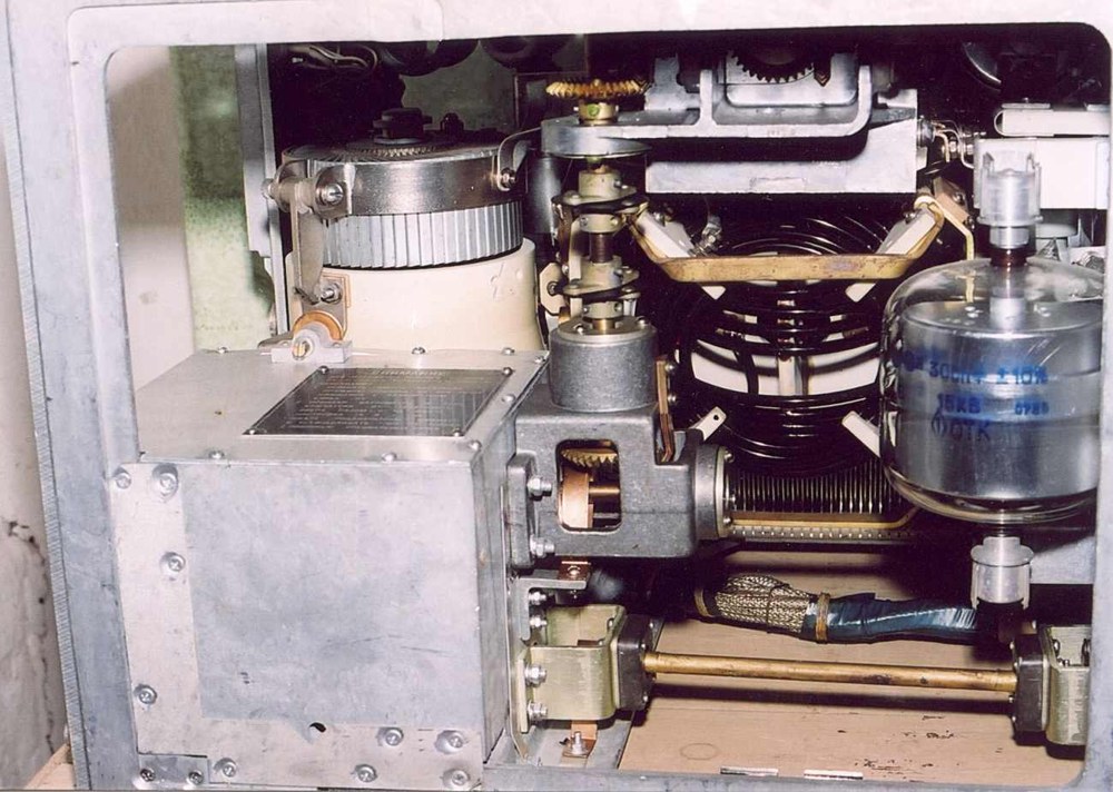
The current transformer and overload protection. The current transformer in the output circuit feeds the output indicator and, with the overload toggle on, the protection circuit. If the antenna mismatches badly — a broken wire, a feeder short, icing — the RF current rises or the anode current jumps, and protection drops high voltage before the GU-43B or the vacuum capacitors fail. [DOCUMENTED] for the components; the protection logic as described is [ESTIMATE].
HOW THE PA IS TUNED
Tuning a tetrode linear by hand is a familiar ham ritual: set the band switch, dip the anode current with the tank tuning, increase loading until the anode current reaches its rated value with maximum output, check the screen current. The R-140 does the same steps, but either the operator does them via the four front-panel knobs while watching the meters, or the automation reproduces stored positions. [BACKGROUND]
For first set-up the RF switch is put in TUNE. The PA output goes into the 50 Ω dummy load, and the USS is connected to a bridge. The operator selects the sub-band, peaks the first stage circuit for grid drive to the GU-43B, tunes the second circuit for resonance (anode current dip, output peak), and then adjusts coupling for full rated loading into 50 Ω. Because the PA is tuned into a known 50 Ω load and the antenna is separately matched to 50 Ω, the two operations are independent — the logic behind the manual's phrase "separate tuning without going on air." Only when both are right does the operator switch to WORK and the PA sees the antenna through the USS. [DOCUMENTED] for the TUNE/WORK method; the step order is [BACKGROUND].
Once the positions are found for a fixed wave they are stored. When that wave is called later, the motors drive the band switch, two variometers and coupling to the stored positions. No RF is needed during that process, so the station can come back on frequency without a tune-up carrier. [DOCUMENTED] / [ESTIMATE]
THE USS AUTOMATIC ANTENNA MATCHING UNIT
The USS, ЯР2.240.001, is the block hams prize most today. It has three tasks: transform the input impedance of "any of the transmitting antennas, both balanced and unbalanced," across 1.5–30 MHz into a 50 Ω resistance equal to the cable impedance between USS and PA; couple the unbalanced transmitter output to balanced antennas; and filter the transmitter's higher harmonics. [DOCUMENTED]
Four sub-bands. I 1.5–4.0 MHz, II 4.0–7.5, III 7.5–16 and IV 16–30 MHz. Note these do not coincide with the PA's five sub-bands; the two blocks are independent, and the PA switch and USS switch are driven separately. [DOCUMENTED]
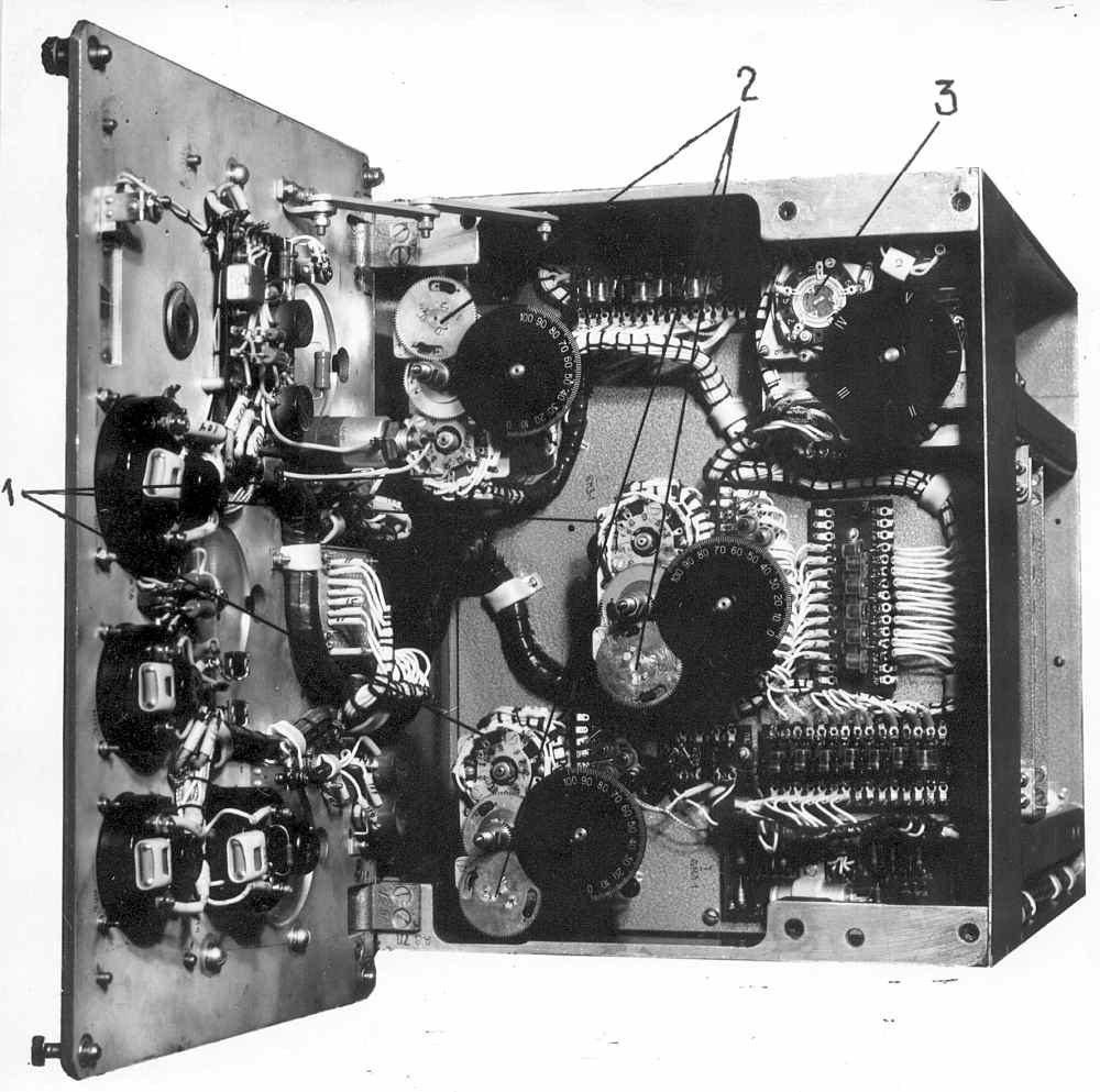
Construction. The USS is a removable block in the upper right compartment of the transmitter rack, built in a cast silumin frame split into two compartments: automation in front and RF components in the large rear compartment. It measures 544 × 446 × 549 mm and weighs 55 kg. [DOCUMENTED]
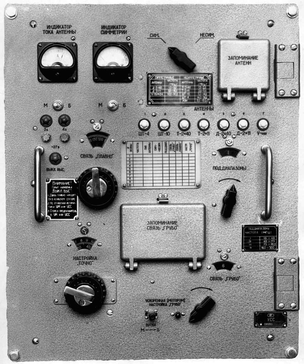
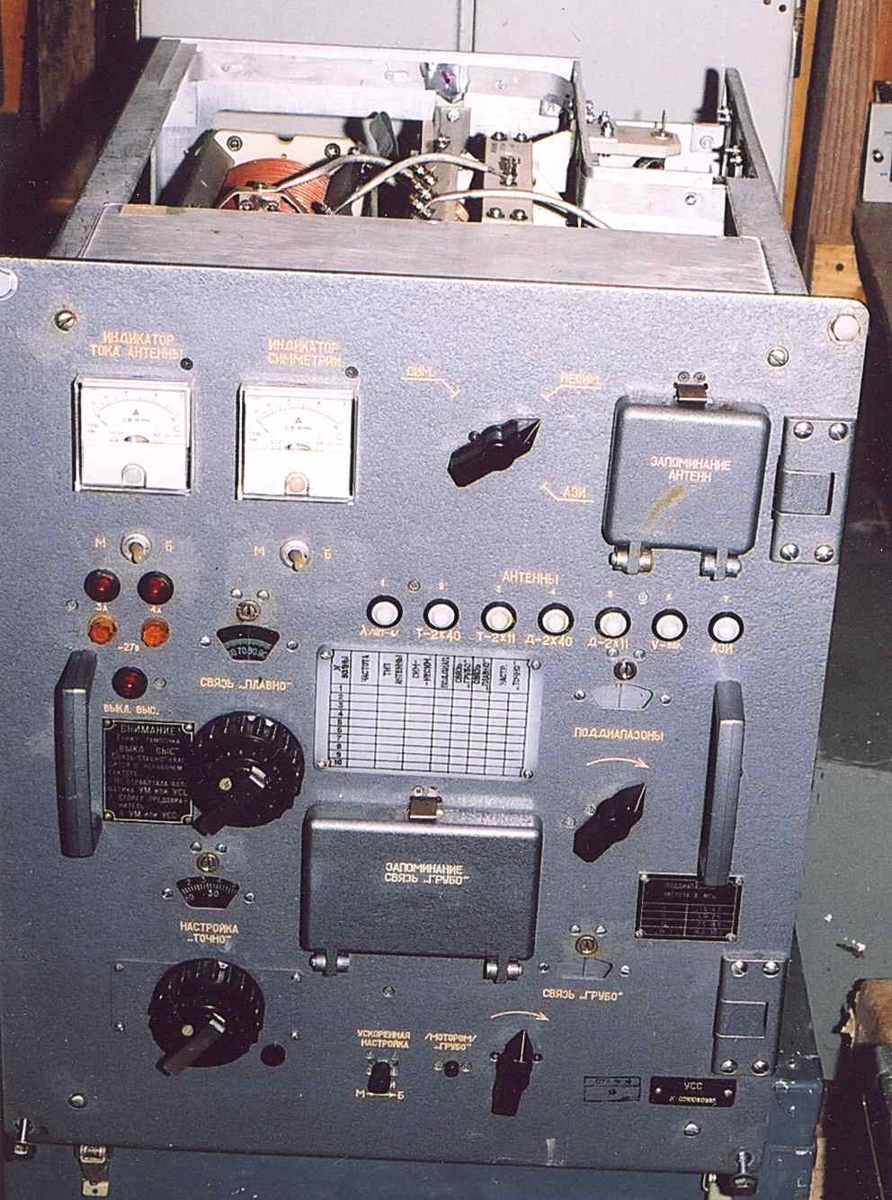
Front panel. Two meters, ANTENNA CURRENT INDICATOR and SYMMETRY INDICATOR, each with its toggle; two switching blocks to memorise the antennas and positions of the COUPLING COARSE switch; eight lamps showing which antenna type is connected; five tuning knobs — BAL / UNBAL / AZI (СИМ.-НЕСИМ.-АЗИ), COUPLING FINE (СВЯЗЬ ПЛАВНО), COUPLING COARSE (СВЯЗЬ ГРУБО), TUNING FINE (НАСТРОЙКА ТОЧНО) and SUB-BANDS (ПОДДИАПАЗОНЫ); two buttons, ACCELERATED (BY MOTOR) and TUNING COARSE; two fuses for the automation supply with blown-fuse lamps; four dial lamps; and the lamp HV OFF that shows high voltage has been cut while the automation moves. [DOCUMENTED]
Inside the RF compartment. Two variable inductors (катушки переменной индуктивности), a capacitor switch, the sub-band switch, the BAL/UNBAL/AZI switch, a variable capacitor, three sets of capacitors, a fixed inductor, three current transformers Tr1, Tr2 and Tr3, and two antenna terminals P1 and P2. [DOCUMENTED]
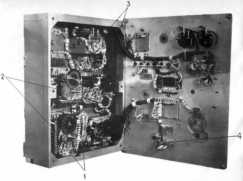
Inside the automation compartment. A PEM-3 drive for the SUB-BANDS switch; a BMZ-2 block that moves the sliding contacts of the variable inductors (TUNING FINE); a PEM-1 drive for switching the COUPLING COARSE capacitors; a BMZ-1 block that rotates the variable capacitor rotor (COUPLING FINE); a PEM-2 drive for the BAL/UNBAL/AZI switch; helical gears on two brackets that drive the sliding contacts of both variable inductors synchronously in the same direction; and a board for the radiation indicator circuit. PEM is an electromechanical drive (привод электромеханический); BMZ is best read as a motor-memory block (блок моторный запоминающий) — a motor plus a position store. [DOCUMENTED] for the parts list; the expansion of BMZ is [ESTIMATE].
HOW THE USS MATCHES AN ANTENNA
The circuit idea. The key fact is that there are two rotary inductors driven together. For a balanced antenna such as the 2×40 m dipole, each leg of the dipole feeds through one of the two inductors, and they must be identical so that the two halves of the antenna carry equal and opposite currents. Ganging them with helical gears keeps them identical. For an unbalanced antenna (whip, T, AZI) the BAL/UNBAL/AZI switch rearranges the network so that the inductors act as a series loading coil against ground. The "coupling" capacitors — a switched coarse bank plus a continuously variable fine capacitor — set the transformation ratio between the 50 Ω input and the antenna's resistance. [DOCUMENTED] for the components; the circuit description is [ESTIMATE] from the parts list and standard practice.
Cancelling reactance. An HF antenna that is shorter than resonance, such as a 10 m whip at 3 MHz, looks like a small resistance in series with a large capacitive reactance. To make it look like 50 Ω resistive, the tuner must first add enough inductance to cancel that reactance — that is the TUNING job of the rotary inductors — and then transform the remaining small resistance up to 50 Ω — the COUPLING job of the capacitors. A long antenna above resonance looks inductive, and the network uses less inductance and different coupling. Covering an antenna set from a 10 m whip to 80 m of dipole across 1.5–30 MHz requires very large ranges of both, which explains the 55 kg block. [BACKGROUND]
Rotary inductors. A rotary inductor (роликовая катушка) is a coil of bare wire or strip wound on a ceramic or plastic cylinder that turns on its axis. A small wheel or sliding contact runs along the turns as the coil rotates, like a nut on a screw, so the number of turns in circuit changes smoothly. A full travel can be dozens of revolutions. That is why the coarse button is labelled "ACCELERATED (BY MOTOR)": a motor spins the coil quickly to the right region, then fine tuning follows. [BACKGROUND] / [DOCUMENTED] for the button.
The sensors. Three current transformers measure RF current in different branches. The ANTENNA CURRENT meter shows current into the antenna: with a fixed antenna resistance, maximum current means maximum radiated power, so the operator tunes for maximum antenna current. The SYMMETRY meter compares currents in the two legs of a balanced antenna via two current transformers; a balanced feed shows equal currents, and any imbalance means feeder radiation, a broken wire or wrong settings. At the PA side, the bridge in the VChP shows whether the USS input looks like 50 Ω. [DOCUMENTED] for meters and transformers; interpretation is [BACKGROUND].
HOW THE SERVO TUNING WORKS
The phrase "automatic antenna tuner" in modern ham gear means a microprocessor that measures impedance and searches for a match in a few seconds. The R-140's USS is automatic in a different, earlier sense: it automatically returns to settings found once, rather than searching from nothing. Understanding that difference explains its behaviour.
Step 1: the first, manual tune. With the VChP in TUNE, low power or a bridge signal applied, the operator selects the antenna type with the BAL/UNBAL/AZI knob (the eight lamps confirm which antenna is plugged into P1/P2), selects the sub-band, presses TUNING COARSE and ACCELERATED to run the rotary inductors to the approximate region, then works TUNING FINE and the two coupling controls to minimise reflected power on the bridge and maximise antenna current, checking the symmetry meter for a balanced antenna. [DOCUMENTED] for the controls; the procedure order is [ESTIMATE] consistent with the "short tuning instruction" ЯР1.201.013 И4 listed in the manual set.
Step 2: memorising. The coarse settings (antenna type, sub-band, coupling coarse step) are discrete switch positions; they are memorised by the two switching blocks on the panel, likely by setting plugs or contacts per fixed wave. The continuous settings — the inductors and fine coupling capacitor — are memorised by the BMZ-1 and BMZ-2 blocks. [DOCUMENTED] / [ESTIMATE]
Step 3: recall. When the station is switched to another fixed wave, the PEM drives step the discrete switches to their stored positions — a classic follow-up switch, in which the motor runs until a wiper on the switch finds a contact marked for that wave and the circuit opens. The BMZ blocks drive the continuous elements back to their stored positions, using a position memory geared to the shaft. During the travel, high voltage is off and the HV OFF lamp is lit. When every drive reports home, HV is restored and the station is ready. [DOCUMENTED] for HV interlock and drives; follow-up switch principle is [BACKGROUND].
Why not search automatically? In the mid-1960s, a closed-loop tuner would have needed phase and magnitude discriminators driving servo motors to null, which was done on aircraft HF sets of the period but is delicate across a huge antenna set and a 20:1 frequency range. The memory approach is robust: a field crew tunes each fixed wave once during deployment, and afterwards the station can hop among ten frequencies on command, even remotely from the VPU 10 km away, with no operator touching the USS. The cost is that a new frequency outside the ten presets needs a fresh manual tune. [SPECULATION]
The SKU for the AZI. The matching-switching unit SKU handles the near-vertical-incidence antenna. It roughly matches the AZI and switches the AZI and the 10 m whip between transmit and receive in simplex. That allows a single antenna to be shared by the transmitter and receiver while the truck is moving, when separate receiving antennas cannot be erected. [DOCUMENTED]
THE ANTENNA FIELD
The R-140 does not have "an antenna." It has an antenna field, laid out over 150 × 100 m, with separate transmitting and receiving antennas so duplex is possible, plus truck-mounted antennas for working on the move. [DOCUMENTED]
Transmitting antennas. [DOCUMENTED]
D2×40 — a balanced sloping dipole of two 40 m legs hung from a single 12 m support. Each leg slopes down from the mast to a ground anchor, forming an inverted V. Eighty metres of wire is a half-wave at about 1.9 MHz, so this is the low-band workhorse for the 1.5–7.5 MHz range.
D2×11 — a balanced sloping dipole of two 11 m legs with its apex at 9 m. A half-wave near 6.8 MHz, used from 4 to 16 MHz.
V 2×46 — a V-shaped travelling-wave antenna with 2 × 46 m legs on a 12.1 m support, used from 7.5 to 30 MHz. A terminated V antenna is directional along the bisector and broadband. Its low-angle radiation suits the longer skip distances at higher frequencies.
T2×40 and T2×11 — T antennas formed from the dipoles by "short-circuiting" the feeder, so the two legs act as the top hat of an unbalanced vertical radiator fed against ground. The large T is used on 1.5–4 MHz and the small T on 1.5–7.5 MHz.
10 m semi-telescopic whip mounted on the vehicle body, used from 4 to 16 MHz, and a 4 m whip on the body.
λ-shaped unbalanced antenna for 16–30 MHz (named in the USS sub-band list).
Receiving antennas. A balanced 2×13 m sloping dipole at 9 m; a V 2×46 m travelling-wave antenna at 12 m; and a 4 m whip on a 12 m mast. Balancing transformers connect unbalanced cables to the balanced receive antennas. The receive antennas are separate from transmit antennas so that in duplex the receiver can listen on one frequency while the transmitter radiates a kilowatt on another. [DOCUMENTED]
Transmit-receive antenna. The two-whip near-vertical-incidence antenna, AZI (антенна зенитного излучения, literally "zenith radiation antenna"), mounted on the vehicle body. [DOCUMENTED]
Which antenna on which sub-band. The USS manual gives the allowed combinations. Sub-band I (1.5–4 MHz): D2×40, T2×40, T2×11, AZI. Sub-band II (4–7.5): D2×40, D2×11, 10 m whip, AZI, T2×11. Sub-band III (7.5–16): D2×11, V 2×46, 10 m whip, AZI in AZI and ShT-4 modes. Sub-band IV (16–30): V 2×46, λ antenna, AZI in ShT-4 mode. [DOCUMENTED]
NEAR-VERTICAL INCIDENCE: THE AZI
The AZI is the most interesting antenna in the set. It is the station's answer to a problem every mobile HF radio faces: the "skip zone." [BACKGROUND]
A vertical whip radiates mostly at low angles. Its ground wave dies within tens of kilometres over typical soil, and its sky wave comes down hundreds of kilometres away. In between is a zone where neither arrives. The 70 km whip range on the move in the R-140 table is essentially the ground-wave limit. [DOCUMENTED] / [BACKGROUND]
A near-vertical-incidence skywave (NVIS) antenna does the opposite. It radiates straight up. At frequencies below the critical frequency of the F layer — typically 2–8 MHz — the signal reflects back down in a broad umbrella, covering 0–300 to 400 km without a skip zone. That matches the manual's figure: on the move with the AZI, up to 300 km. [DOCUMENTED] / [BACKGROUND]
The R-140's AZI is two whips on the vehicle body, fed as a pair. The usual Soviet arrangement (also used on the R-161 and other command vehicles) is to fold whips over horizontally or tilt them so the radiating current is largely horizontal close to the vehicle roof, which radiates upward. The museum's two "travelling position" drawings show the R-140 configured for the ShT-4m whips and for the AZI. The USS operating mode list shows that the AZI is used in AZI mode (true NVIS, on the lower bands) and in ShT-4 mode (as two 4 m whips, on the higher bands, where NVIS would penetrate the ionosphere). [DOCUMENTED] for the modes; the physical whip arrangement is [ESTIMATE].
THE RECEIVER: R-155P
The receive side is a separate device, the R-155P receiver with a receive-antenna switch and a BSP block. The museum quotes sensitivity at a 3:1 signal-to-noise ratio: in narrow telegraph (TLG-U, 260 Hz bandwidth) 0.6 µV on 1.5–5 MHz, 0.5 µV on 5–20 MHz and 0.3 µV on 20–30 MHz; in wide telegraph (TLG-Sh, 1.2 kHz) 1.3, 1.1 and 0.6 µV; in DSB telephone at 30 % modulation, 12, 10 and 5.5 µV. All teleprinter FSK and DFSK modes are better than 1.5 µV across the range. [DOCUMENTED]
The receiver uses the same synthesised 100 Hz grid and the same ten-fixed-wave memory as the transmitter. The pair can be used in simplex (same frequency) or duplex (frequencies separated as described above). The R-155 family was a common Soviet HF receiver used in several station types. [DOCUMENTED] / [BACKGROUND]
The "dual reception" (сдвоенный прием) needed for the 2500 km aircraft range is space or frequency diversity: two receiving channels on different antennas feed a combiner that picks the stronger signal as fading moves between them. [DOCUMENTED] for the term and range; mechanism is [BACKGROUND].
POWER SUPPLY AND GENERATORS
The station needs not more than 5 kW from the mains and not more than 4 kW from the generator or PTO. The kilowatt RF output is the visible part; the rest goes to the PA's anode dissipation, the GU-43B heater, the exciter ovens, the receiver, blowers, motors, lighting, heating and battery charging. [DOCUMENTED] / [BACKGROUND]
Sources. Three-phase industrial mains at 50–60 Hz, 220 or 380 V; the AB-4-T/230 petrol-electric set, a 4 kW three-phase 230 V generator, used at the halt and on the move; and the truck engine's power take-off, used at the halt as a reserve. The VPU trailer has an AB-1-O/230, a 1 kW single-phase set, or uses 220 V single-phase mains. [DOCUMENTED]
Power equipment. Automatic switch-on and network protection (АВЗС / ABV), voltage stabiliser, distribution board RShch, distribution box, rectifiers and batteries. [DOCUMENTED]
Batteries. Two 2KN-24 batteries and two 4KN-14, one working and one spare of each. The 2KN-24 runs the R-311 standby receiver; the 4KN-14 runs the R-105M VHF set. A rectifier in the RShch charges them, and they sit for charging in the AB-1 compartment. The radio remote control panel RVPU has its own 4KN-10 battery or runs from 220 V. These are nickel-cadmium cells of standard Soviet sizes. [DOCUMENTED]
The VU-50 rectifier. Supplies the PA valves and the automatic retuning drive. In other words, the high voltage for the GU-43B anode and screen, plus the motor and relay supply, come from this one block. That ties the HV interlock and the automation together physically. [DOCUMENTED]
Why a voltage stabiliser. A small petrol generator's voltage swings with load. When the PA keys up from idle to a kilowatt output, the anode supply draws a sudden 1.5–2 kW; without regulation the exciter and receiver supply would sag, shifting oscillator frequencies and upsetting SSB. The stabiliser isolates the sensitive circuits from these swings. [SPECULATION]
COOLING AND THE SHELTER ENVIRONMENT
The GU-43B is a forced-air-cooled valve; its anode is surrounded by a finned radiator through which a blower drives air. At full output an AB1 amplifier dissipates several hundred watts in the anode, more on key-down in CW or FSK. Every fixed position also adds heat from the heater and screen. The rack design pulls air through the PA, and the shelter needs ventilation to carry the heat outside. [BACKGROUND] / [ESTIMATE]
The manual rates the equipment for a shelter temperature from −10 °C to +50 ±2 °C at 65–68 % relative humidity, or not above +32 °C at 95–98 % humidity. The O-30 heater handles the cold end; the oven-controlled crystals need an hour to settle, which is why full-mode readiness is one hour after switch-on. [DOCUMENTED]
Teleprinter traffic is the hardest duty because FSK is a constant-envelope, continuous carrier: the PA delivers full power all the time rather than at the average of speech peaks. A conservative operator would run FSK below full rating on long messages in summer. [SPECULATION]
CONTROL: THE PUR AND REMOTE POSTS
The R-140 was never meant to be run only from inside the truck. The manual lists seven control points. [DOCUMENTED]
From the operating compartment, via the PUR (пульт управления радиостанцией): power for the whole station; tuning to any frequency; preparing ten fixed waves for transmitter and receiver; passing control to the RVPU, VTS, cab and so on; switching power sources; calling and service telephone to the remote posts; aural reception on the R-311; one- and two-channel SSB telephone; FM telephone; hand Morse with amplitude and frequency keying; and one- and two-channel telegraph in duplex or "simplex with break-in." [DOCUMENTED]
From the remote control post VPU in the trailer, up to 10 km away via the R-405P-T1 relay or P-271M cable lines: selecting any of the ten fixed waves of the transmitter and of the receiver; switching station power on and off (if it is already on in the operating compartment); switching transmitter HV; switching between receive and transmit; monitoring that commands are executed; choosing telegraph or telephone; and full traffic handling in all modes. This is where the telecontrol/telesignalling (ТУ-ТС) system comes in: commands go out from the VPU dispatcher device and status comes back. [DOCUMENTED]
From the RVPU, a radio remote control panel up to 1 km from the truck or VPU by cable: service talk with the operating compartment, simplex single-channel SSB and FM telephone, and simplex Morse. From a TA-57 telephone up to 500 m away: service talk and simplex telephone. From a military telegraph station (VTS): service talk by telephone or by the STA-M67B, and one- and two-channel teleprinter in simplex with break-in or duplex. From a remote R-405P-T1: one- or two-channel duplex telephone or telegraph. From the driver's cab: simplex single-channel telephone, service talk, and working via the R-105M. [DOCUMENTED]
A special adapter allowed simplex telephone over the relay, with the push-to-talk state sent over the second telegraph channel so the R-140 switched between receive and transmit as the distant operator pressed the microphone switch. [DOCUMENTED]
Why so much remote control? A kilowatt HF transmitter is a beacon to enemy direction-finding. Soviet doctrine placed transmitters and receivers away from the command post, linked by relay or cable, so that a strike on the emitter would not destroy the headquarters. The R-140D's 10 km trailer is that doctrine in hardware. [BACKGROUND]
LINK TO COMMAND NETWORKS
The R-140 served "in front and army nets" and could work "in the system of communication centres of mobile control points, and autonomously." [DOCUMENTED] In practice that means two roles.
As part of a communication centre (узел связи). A front or army field command post had a communications centre with a radio-transmitting site, a receiving site, a relay node and a telegraph/telephone exchange. R-140s sat in the transmitting group, their traffic arriving from the exchange through relays or cables, and their keying controlled from the VTS. The station's line input and the ability to take traffic from external telephone and telegraph equipment make it a bearer in that structure. [DOCUMENTED] / [BACKGROUND]
Autonomous. On the move, or when detached to a subordinate formation, the station worked alone: AZI on the roof, operator in the shelter or cab, Morse or SSB direct to the higher headquarters. [DOCUMENTED]
Users named in the manual are the ground forces, Strategic Rocket Forces, PVO Strany (national air defence) and air force. For the rocket forces and air defence, HF links like this one were backup to cable and relay for alerting and reporting; for the air force, the ability to talk to airborne SSB stations at 2500 km was a direct ground-air requirement. [DOCUMENTED] for the user list; roles are [BACKGROUND].
CREW OPERATION: A DEPLOYMENT WALK-THROUGH
The following sequence is reconstructed from the documented crew, timings, antenna set and control functions. Detailed steps in the instruction ЯР1.201.013 И and the short tuning instruction И4 may differ in order. [ESTIMATE]
Arrival. The truck arrives at the site chosen by the signals officer: about 150 × 100 m of open ground, away from the command post. The driver-electrician starts the AB-4 generator or connects to mains, checks phase rotation and voltage on the stabiliser and distribution board, and powers up the shelter. The exciter ovens begin warming at once; this starts the one-hour clock for full-mode readiness. [DOCUMENTED] for the area, sources and warm-up.
The antenna crew. The station chief and two radio-telegraphists erect the masts and antennas: the 12 m mast for the 2×40 m dipole, the 9 m support for the 2×11 m dipole, the 12.1 m mast for the V travelling-wave antenna, the receiving dipole and V, the 12 m mast with the receiving whip. Guys, pegs, insulators, feeders and balancing transformers are laid out. The whole job takes 2 hours 30 minutes in summer for a trained team. Winter, frozen ground, or a short crew add time. [DOCUMENTED] for the duration; the division of labour is [ESTIMATE].
Interim working. After 20 minutes the station can work 70 %-carrier SSB and aural Morse — enough to report "on air" to the net control on the AZI or whip while the field antennas go up. [DOCUMENTED]
Preparing fixed waves. From the communications plan, the chief knows the frequencies assigned for day, night and transition. For each, a fixed wave is prepared: set the frequency on the 1-0M decades, select the mode on V-3, set the exciter output level, tune the PA into the dummy load, connect the planned antenna and tune the USS on the bridge, record and store. With ten waves this is a substantial job, but it is done once per deployment. [DOCUMENTED] for the stored parameters; workflow is [ESTIMATE].
Traffic. Traffic comes from the VTS teleprinter or from telephone lines. In duplex, the receiver listens on the paired receive frequency on its own antenna. Operators keep a log, check frequency against time signals, and change waves on the schedule or on order. Remote control is handed to the VPU if the R-140D trailer is deployed. [DOCUMENTED] / [BACKGROUND]
Moving. To work on the move, the field antennas come down, the AZI whips go up (5–10 minutes), and the station works up to 300 km by NVIS or 70 km on a whip, with the driver's cab panel available for simplex telephone. [DOCUMENTED]
A SIMPLE LINK ESTIMATE
To show why the documented ranges make sense, take a night link of 1200 km at 7 MHz, R-140 to R-140, using the V 2×46 antennas. [ESTIMATE]
Transmitter output about 900 W, or about +59.5 dBm. Antenna gain for a terminated V at moderate height, perhaps 3–6 dBi toward the bisector, after its termination losses. Path loss for a single-hop F-layer path of 1200 km: free-space spreading loss around 111 dB at 7 MHz, plus 10–20 dB of absorption and ground reflection depending on time and season, giving about 125–130 dB. Received signal at the R-155P input therefore roughly −60 to −70 dBm, or around 70–220 µV on 50 Ω. Atmospheric and man-made noise at 7 MHz at night in a 3 kHz bandwidth is commonly around −100 to −110 dBm at a quiet rural site. That gives an SSB signal-to-noise ratio of 30–40 dB in good conditions — a comfortable voice link with a margin for fading. In Morse with a 260 Hz filter, the noise drops by another 10 dB, which is why the manual quotes 2000 km for aural telegraph. [ESTIMATE]
The same calculation for a 10 m whip on the move at 3 MHz at 70 km is dominated by ground-wave loss and whip efficiency below 10 %. The AZI improves this by choosing NVIS geometry. These are the physical reasons behind the manual's numbers. [ESTIMATE]
HISTORY
Development. The R-140 belongs to the second generation of Soviet post-war HF command radios, developed in the early-to-mid 1960s as SSB became the standard for military HF worldwide. The 1967 spectral passport and the 1968 first edition of the technical description give an upper bound for completion of the design. [DOCUMENTED] for the dates; the generational framing is [BACKGROUND].
Designer and manufacturer. The "ЯР" decimal-classification prefix on the documents (ЯР1.201.013, ЯР2.068.071, ЯР2.240.001) is usually associated in Russian collector literature with the Yaroslavl radio plant (Ярославский радиозавод), which also built other military radios. We did not find a primary document naming the developer institute. [SINGLE-SOURCE]
Secrecy. The technical description carries the suffix "С" (секретно, secret). It was declassified by MoD order No. 0105 of 15.05.1985, when the R-140 was still in service. That timing suggests the technical secret was considered to be in the newer M version and in the communication plans, not in the basic radio. [DOCUMENTED] for the order; interpretation is [SPECULATION].
Modernisation. The R-140M with the VO-71B exciter followed in the 1970s; its technical description is from 1982. The R-140M-1 description is from 1977. The family remained in production and service into the 1980s and was handed to successor states in 1991. [DOCUMENTED] for the documents; production span is [ESTIMATE].
Service and export. R-140 stations served throughout the Soviet Army, the Warsaw Pact (the GDR-built PA block in the museum is evidence of East German production or assembly), and client states that received Soviet signals equipment. They appear in photographs from Afghanistan in the 1980s and in post-Soviet armies. Specific deployments beyond these general statements are [UNVERIFIED]. [DOCUMENTED] for GDR block; rest [UNVERIFIED].
THE MANUALS
The museum's lists give a near-complete document set. [DOCUMENTED]
Radio station R-140 (R-140D). Technical description. Book 1. ЯР1.201.013 ТО/С. Edition 1-68. Declassified by MoD USSR order No. 0105 of 15.05.1985.
R-140 (R-140D). Technical description. Book 2. ЯР1.201.013 ТО/С. Edition 3-69.
R-140 (R-140D). Technical description. Book 3. Switching system and control panel. ЯР1.201.013 ТО/С. Edition 3-71.
Product R-140 (R-140D). Technical description. Book 4. Power sources. ЯР1.201.013 ТО. Edition 2-68, 1968.
R-140 (R-140D). Operating instruction. ЯР1.201.013 И. Edition 3-68.
R-140 (R-140D). Operating instruction. ЯР1.201.013 ИЭ. 1973.
R-140 (R-140D). Supplement to the operating instruction. ЯР1.201.013 И/с. Edition 1-68.
Product R-140 (R-140D). Short tuning instruction. ЯР1.201.013 И4. Edition 3-70.
R-140 (R-140D). Spectral passport. 1967.
R-140 (R-140D). Album No. 1 and Album No. 2. Electrical schematic diagrams. ЯР1.201.013-Оп1 / -Оп2 (Album 2 dated 1969). Product R-140 (R-140D). Album of schematic diagrams. Volume IV, Part II.
Maintenance schedule for the R-140. ЯР1.201.013 ИО. 1973.
Group spares set for the R-140. Spares list. ЯР4.068.855 ДЗ.
R-140M. Technical description. ЯР1.600.004 ТО. 1982.
R-140M-1. Technical description. ЯР1.600.013 ТО. 1977.
Product "Bereza". Technical description and operating instruction. ЯР1.600.020 ТО, 1982 (and ИЭ, 1977).
Reading these is the only reliable path for anyone restoring a block. Scanned DjVu copies of some books circulate on Russian radio sites. [SINGLE-SOURCE]
SURPLUS: R-140 PARTS IN HAM SHACKS
When the post-Soviet armies wrote off R-140 stations, the blocks scattered into the amateur world, and they are still among the most sought-after Soviet military surplus for HF hams. [BACKGROUND]
The GU-43B. The GU-43B, from R-140 PAs and spares kits, is a staple of Russian, Ukrainian and Eastern European home-built kilowatt amplifiers. It needs only modest drive in grounded-grid service, suits the 1.8–28 MHz amateur bands, and is rugged. Homebrew designs usually run it at 2.5–3 kV with a pi or pi-L tank circuit and a blower. The tube is still widely traded. [BACKGROUND]
The complete PA block. Some amateurs have used the whole UM drawer, with its motor drives removed, as a ready-made linear amplifier, adding a power supply and rewiring for 50 Ω input. The variometer tuning makes it bulkier to operate than a pi network but very robust. [SINGLE-SOURCE]
The USS tuner. The USS is valued above all for its two big rotary inductors, its vacuum and high-voltage capacitors, and its symmetrical output: a true balanced tuner rated for a kilowatt from 1.5 to 30 MHz is exactly what an operator feeding a doublet with open-wire line wants. Many USS units have been stripped for their inductors and capacitors; complete units are heavy at 55 kg and need their 27 V-class motor supply or hand cranks to be useful. [DOCUMENTED] for the weight and function; voltage of the motor supply is [UNVERIFIED].
Vacuum capacitors, meters, motors. The PA's vacuum capacitors, the meters with their Cyrillic scales, and the electromechanical drives are prized components in their own right. [BACKGROUND]
A caution. R-140 power supplies operate at lethal voltages, and old electrolytic and paper capacitors in the VU-50 should be checked before any power-up. Surplus blocks have often been cannibalised; a "complete" USS on a sale listing may be missing the memory blocks. [BACKGROUND]
COMPARISON: R-140 AND R-161
The R-161 family is the natural successor and comparison inside the Soviet system. R-161 stations (for example R-161-5, R-161-2M and later variants) are high-power mobile HF/ionospheric stations of the 1970s–80s for front- and strategic-level links. Open sources credit the larger members with several kilowatts of output — the "-5" suffix is usually read as 5 kW — and with more automation, wider use of solid-state circuits and later digital control. They used the same general ideas as the R-140: separate transmitting and receiving complexes, NVIS antennas on the vehicle, sloping dipoles and travelling-wave antennas on masts, remote control posts. [SINGLE-SOURCE] for R-161 power and dating.
Where the R-140 is a one-truck, one-kilowatt operational station, the R-161 class is generally described as a multi-vehicle complex with higher power and more channels. The R-140 kept a role at army and corps level and in service branches, alongside the R-161 at the top of the hierarchy. We did not have an R-161 technical description to compare the tuners and exciters directly, so finer comparisons are [UNVERIFIED].
The R-140 also sits above lighter tactical HF sets. The vehicle and command-post sets with tens to hundreds of watts that a division or regiment used talked to it on common frequencies and modes, which is precisely why the R-140 keeps 70 % carrier modes and FM. [SPECULATION]
COMPARISON: WESTERN EQUIVALENTS
United States: AN/GRC-26D and AN/GRC-106. The US Army's 1950s mobile teletype station AN/GRC-26D used the BC-610 transmitter, about 400 W on AM and CW, hand-tuned, with crystal or VFO frequency control and no SSB. Its 1960s replacement for command nets was the AN/GRC-106, a Collins-designed 400 W SSB transceiver (AN/GRC-106 with the AM-3349 amplifier) covering 2–30 MHz with 1 kHz synthesised steps (later 100 Hz in the A model) and automatic servo tuning of the PA. Radio-teletype rigs such as the AN/GRC-122 and AN/GRC-142 put the GRC-106 in a shelter with teletype and crypto. [BACKGROUND]
Against the GRC-106, the R-140 has more than twice the power, a lower frequency limit (1.5 vs 2 MHz), finer 100 Hz steps from the start, two-channel SSB and DFSK, and a whole antenna field with balanced antennas. The GRC-106 is far smaller and lighter — it fits a jeep — and its synthesiser and servo tuning are faster. The R-140 is a station; the GRC-106 is a radio. [BACKGROUND] / [SPECULATION]
Larger US equipment. Comparable American kilowatt-class mobile HF sets of the period existed in signal battalion vans and Air Force mobile communication complexes, often built around Collins or Technical Materiel Corporation transmitters. [BACKGROUND]
Britain and West Germany. The British Army's Larkspur-era high-power sets and later Clansman-era vehicle stations, and Bundeswehr kilowatt HF shelters built around Rohde & Schwarz or Telefunken transmitters, filled the same niche. Western sets of the 1970s typically had broadband solid-state drivers and faster automatic tuners; the R-140's valve PA and memorised mechanical tuner are a generation older in feel but very rugged. [BACKGROUND] / [SPECULATION]
The common pattern. All armies converged on the same solution in the 1960s: SSB with a stable synthesiser, a linear amplifier, automatic retuning of the output stage, and multiple antennas including NVIS for short ranges. The Soviet distinctive choices in the R-140 are the high power for the class, the elaborate remote-control system, the selectable carrier for compatibility with an old fleet, and the heavy, memory-driven mechanical tuner. [SPECULATION]
STRENGTHS AND WEAKNESSES
Strengths. Stability adequate for SSB without searching. One kilowatt in a single truck. Ten pre-set frequencies with automatic retune. Two-channel voice and telegraph. Separate receiving antennas allowing duplex. Remote operation up to 10 km. Large antenna set covering ground wave, NVIS and long-range sky wave. A matching unit that handles balanced and unbalanced antennas. Compatibility with old AM sets and with aircraft. [DOCUMENTED] for the features; the judgment is [SPECULATION].
Weaknesses. A full hour of warm-up for all modes. Two and a half hours to deploy the full field. 30–40 seconds to change frequency, too slow for anything resembling frequency hopping. Only ten waves without manual re-tuning. A large, emitting, easily located signature. Heavy maintenance load on motors, gears, contacts and valves. No built-in crypto or data modem. By the 1980s the R-140 was outclassed in speed and automation by newer equipment, though it remained a dependable bearer. [DOCUMENTED] for the times; the judgment is [SPECULATION].
WHAT TO LOOK FOR IN THE PHOTOGRAPHS
The transmitter racks. The R-140 rack shows the exciter at the top left, the frequency decades and display, the PA drawer with its three meters, the USS drawer with its two meters and row of antenna lamps, and the lower power and switching cabinet. The R-140M rack has the same layout with a different exciter front. [DOCUMENTED] that these are the respective racks; position labels are our reading of the photographs [ESTIMATE].
The PA drawers. The R-140 and R-140M PA fronts differ in meter layout and panel details but carry the same controls: sub-band switch, two tuning knobs and coupling. The open and top views show the bevel-geared band switches, variometers and vacuum capacitors described above; the internals view shows the GU-43B socket area, chokes and output network. [DOCUMENTED] / [ESTIMATE]
The USS. The front panel shows the antenna current and symmetry meters, the eight antenna-type lamps and the five controls. The open view shows the two ganged rotary inductors and switch assemblies behind the hinged front panel. [DOCUMENTED] / [ESTIMATE]
MAINTENANCE AND COMMON FAULTS
The museum lists a separate maintenance schedule document, Регламент технического обслуживания радиостанции Р-140, ЯР1.201.013 ИО, dated 1973. Its contents are not online. From the construction, the obvious maintenance points are these. [ESTIMATE]
WHAT THE R-140 CHANGED
The R-140 is one of the stations that took Soviet tactical HF from the era of searching by ear to the era of frequency discipline. With every R-140 and R-155P on the same 100 Hz grid, a front-level net could be planned like a telephone exchange: a frequency plan was issued, each station set it, and SSB voice and teleprinter traffic flowed without hunting. UA0SQ calls the R-140 and R-155P a generational leap, comparing the R-155P to the earlier R-154-2M and asking how such a jump could have happened so quickly. [SINGLE-SOURCE]
Its service life was long: the R-140M in the 1970s and 1980s, the R-140M-2 and DM-1 variants later, and widespread export across the Warsaw Pact. It was still in use long after the Soviet Union ended, and it is still familiar to anyone who served in Soviet or post-Soviet signals units. [ESTIMATE as to the length of service]
SOURCE CONFLICTS
A WORKED EXAMPLE: DUSK CHANNEL CHANGE
This is an illustrative reconstruction, not a quoted procedure [ESTIMATE].
It is 17:40 local time in autumn. An R-140 at an army headquarters is working its front headquarters 900 km away on channel 3, 11.4 MHz, single-channel SSB, on the D2×11 dipole. Signal reports are getting weaker as the maximum usable frequency on the path falls toward sunset. The schedule calls for channel 6, 6.9 MHz, also SSB, on the same dipole.
The operator tells the far station on voice to move to channel 6, waits for acknowledgment, and selects channel 6 on the control desk. The HIGH VOLTAGE OFF lamp on the USS lights. On the exciter, the decades jump to 6.9000 MHz and V-3 sets SSB. In the PA, the sub-band switch moves from IV (10–16 MHz) to III (5–10 MHz), turning the bevel-gear train so that the first-stage switch moves too; the two variometers run to their stored stops for 6.9 MHz. In the USS, the sub-band switch moves from III (7.5–16) to II (4.0–7.5); the BAL./UNBAL./AZI switch stays on balanced because the antenna is the same; COUPLING COARSE changes capacitor bank; BMZ-1 rotates the COUPLING SMOOTH capacitor and BMZ-2 drives both roller inductors to their stored positions. After about 35 seconds the lamp goes out, high voltage returns, and the operator calls the far station on channel 6.
If the far station replies weakly, the operator might suspect the dipole has changed (wet ground, sagging leg) and do a quick retune into the bridge: HF switch to TUNE, PA on the dummy load, nudge TUNING FINE and COUPLING SMOOTH for a null, back to WORK, and re-store the new positions.
TWO DETAILS HAMS SHOULD COPY
The USS front panel carries a lamp labelled HIGH VOLTAGE OFF, which lights while the tuning automatics are running [DOCUMENTED]. The station removes anode voltage every time a motor moves a switch, variometer or roller inductor, so nothing is ever switched hot. Any home-built remote or motor-driven tuner should use the same interlock.
The R-140 anode transformer is heavy and conservatively rated. The RZ3AH 5–6 kW amateur stage on two GU-78B tetrodes (cqham.ru) calls for "two R-140 transformers in parallel, with small modifications" for its 3 kV anode supply [SINGLE-SOURCE]. That is very likely how "R-140" and "GU-78B" got linked in ham folklore.
RELATED
Vyaz-M2 — 5 kW stationary HF transmitter on two GU-5B triodes; its Vyaz-M2-OP upgrade used the R-140's VO-64 exciter.
R-631 Plamya — naval HF transmitter with a parallel GU-84B final.
R-187 Azart
R-173 Abzats
R-168 Akveduk
CROSS-REFERENCES
For the tactical end of the Soviet and Russian radio spectrum, compare the R-173 vehicle VHF set, the R-168 Akveduk family and the R-187 Azart SDR handheld. The R-140 is the opposite end: a fixed-frequency-plan, high-power HF bearer for headquarters, not a frequency-hopping net radio. [BACKGROUND]
IN ONE SENTENCE
The R-140 is a 1960s Soviet one-kilowatt truck-mounted HF station — crystal-referenced 100 Hz synthesiser, multi-mode SSB/FSK/Morse exciter, a GU-43B class AB1 power amplifier (not GU-78B or GU-84B) and a 55 kg USS balanced matching unit with ganged motor-driven rotary inductors that recalls ten memorised antenna settings in 30–40 seconds — feeding a full field of dipoles, V antennas, whips and an NVIS roof antenna, controllable from a trailer 10 km away, and later a favourite source of tubes and tuners for Eastern European hams.
SOURCES
Museum of Non-Consumer Electronics (radioscanner.ru): Radio station R-140 (R-140D) overview; Transmitter of the R-140; Power amplifier of the R-140; Matching-balancing unit of the R-140 — all quoting the declassified manual set listed above. Photographs in this article are from the museum's R-140 pages (CC-BY-SA-2.5 licence as stated on the museum site). [DOCUMENTED]