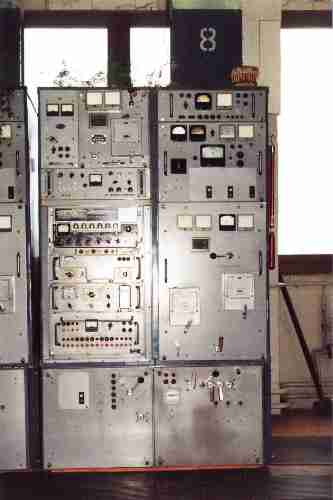
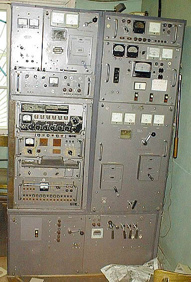
WHAT IT IS
Vyaz-M2 (Вяз-М2, "Elm") is a Soviet 5 kW shortwave transmitter from the start of the 1960s. It was one of the workhorse HF transmitters of the Soviet state: installed at manned and unmanned fixed radio centres, carried inside mobile radio stations of the Ministry of Defence, fitted to Navy ships and to the space-tracking ships of the Soviet Academy of Sciences, and, in one of its best-known jobs, used as a groundwave jammer against Western broadcasts at stations such as Panevėžys in Lithuania [DOCUMENTED for fixed, mobile, ship and Panevėžys use, from the sources below].
In technical terms it is a three-stage, all-tube, push-pull HF transmitter covering 3 to 24 MHz (2 to 24 MHz in some course material), putting out at least 5 kW in telegraph and at least 2.5 kW carrier in AM telephone into a balanced load, from a 380 V three-phase supply drawing about 20 kW. The whole installation weighs about 1,000 kg [DOCUMENTED, factory history page; course notes; radioscanner.ru review]. Its RF chain is 2 × GU-50 in a wideband first stage, 2 × GU-80 or GU-81 in a push-pull resonant driver, and 2 × GU-5B triodes in a push-pull resonant final [DOCUMENTED, factory history page; consistent with radioscanner.ru and RZ3AH].
For radio amateurs, the Vyaz-M2 is famous for a different reason. Its output stage, with two big triodes, a series-fed balanced tank and a split-stator capacitor whose plates move toward each other, is regarded as one of the best-engineered big HF stages the Soviet industry ever built. Russian hams have rebuilt it to 15 kW with GU-35B tetrodes, and a well-known reviewer said simply that he envied anyone who could keep "such a beast" [SINGLE-SOURCE for the reviewer quote; SINGLE-SOURCE for the 15 kW conversion].
SOURCES AND HOW MUCH TO TRUST THEM
Four kinds of source are used here:
Factory history page ("Изделие «Вяз»", hosted on a Krasnoyarsk television-plant veterans' site). It gives the developer, the factory, the start of production, the full technical characteristics, the RF line-up and photographs of each stage. It is the most complete single description found and is treated as [DOCUMENTED] for figures, because the same figures appear in independent military-college course notes.
Course notes (Russian signals-school material, question 87 "Structural diagram of a communications transmitter, using the Vyaz-M2 as the example"), which repeat the main figures with a 2–24 MHz range, a 2.4 kW telephone figure and an efficiency of at least 30 % [DOCUMENTED].
Ham reference pages: cqham.ru's short entry by UR3IRS and UA1OSM (5 kW, GU-5B final, AM/CW/RTTY, no SSB), the RZ3AH page on 5–25 kW HF output stages, and a long radioscanner.ru user review [SINGLE-SOURCE each, though they agree with one another and with the factory page].
Jamming archive: Rimantas Pleikys's "Jamming" site (oldradio.lt), which captions a photo as "Typical groundwave jamming equipment — communications transmitter VIAZ-M2-OP (5 kW), Panevėžys (Lithuania) jamming station." Pleikys was later Lithuania's minister of communications and assembled the archive from the dismantled stations [DOCUMENTED for the caption; BACKGROUND for the author].
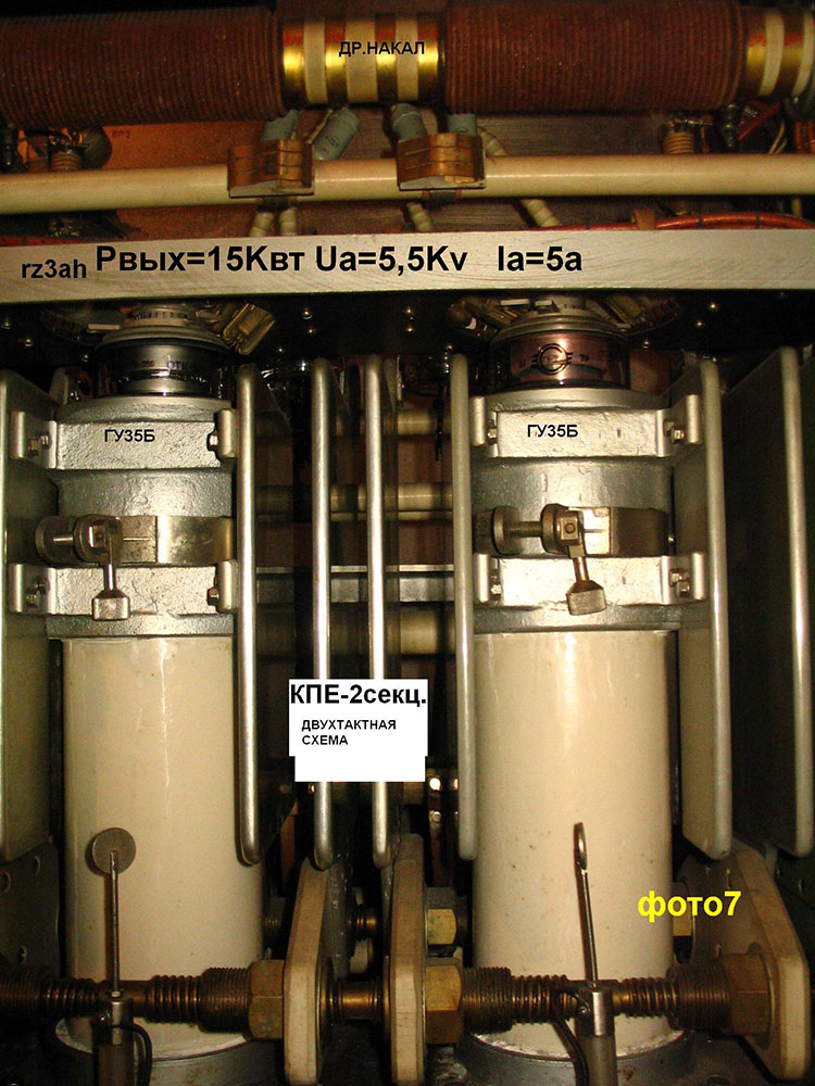
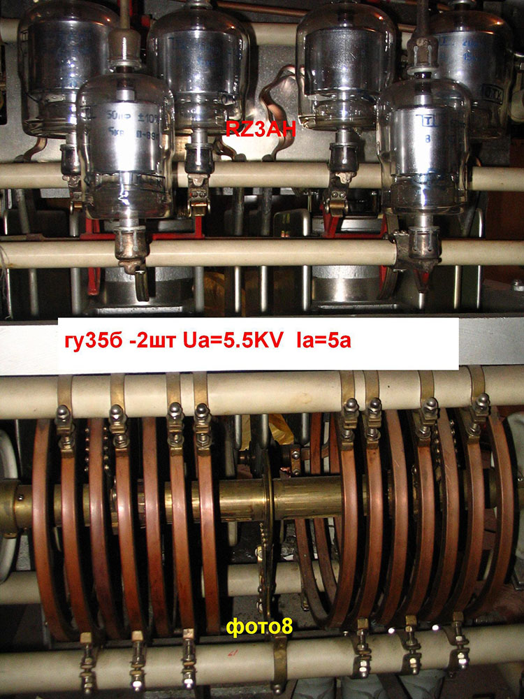
Photo note: two of the pictures in this article come from RZ3AH's page and show the output block of a Vyaz-M2 that the author used as a base for his own high-power amateur stage. The labels written on those photos are his. The block shown may not be in factory condition; see the ham section.
HISTORY, DEVELOPER AND FACTORY
The factory history states that the Vyaz-M2 was developed by the Leningrad VNIIMR (Всесоюзный научно-исследовательский институт мощного радиостроения, the All-Union Research Institute of High-Power Radio Engineering), and that series production was by the Krasnoyarsk Television Plant in assembly shop No. 7, from 1961. The factory code for the product was simply "Vyaz" [DOCUMENTED, single factory source].
VNIIMR is the institution behind a long line of Soviet high-power transmitters for broadcasting, communication and the Navy. Its successor company, the Russian Institute of High-Power Radio Engineering (St Petersburg), is named as the maker of the R-631 naval transmitter in the open-press catalogue Russia's Arms and Technologies [DOCUMENTED that the catalogue names it; BACKGROUND for the VNIIMR lineage]. In other words, the Vyaz-M2 and the R-631 Plamya described in a companion draft come from the same design house, a generation apart.
The "Krasnoyarsk Television Plant" sounds like an odd place to build military transmitters, but Soviet consumer-electronics plants routinely had defence shops; the television name was the public face [BACKGROUND].
The factory page says the transmitter was intended "for operation on radiotelephone and radiotelegraph communication lines" and was installed "at stationary unattended and attended radio stations, at mobile radio stations of the Ministry of Defence, and on ships of the Navy" [DOCUMENTED]. It also records that in 1970–1971, under projects "Phoenix" and "Canopus," Krasnoyarsk specialists and the plant's design office installed several Vyaz-M2 transmitters on the research ships Kosmonavt Yuriy Gagarin and Akademik Sergey Korolev, the floating mission-control centres of the Soviet space programme [DOCUMENTED, single factory source]. Those ships needed reliable HF links to Moscow from the middle of the Atlantic, and the Vyaz-M2 was the proven 5 kW unit for the job.
The radioscanner.ru reviewer says the Vyaz-M2 was part of the mobile radio station R-110 "Osina," and that a 25 kW "older brother," also called Vyaz with a letter suffix he was not sure of (possibly "Vyaz-M2USB"), was part of the R-100 (M, M2) mobile station [SINGLE-SOURCE; suffix explicitly uncertain by the reviewer].
The factory page closes with the claim that "many years of operation of transmitters of this type showed that they were among the most reliable and long-lived in the country" [DOCUMENTED as the factory's claim].
TECHNICAL CHARACTERISTICS
From the factory history page [DOCUMENTED]:
Exciter type: VT-53 (or VT-44) "Tantal"; VD-23.
Frequency range: 3 to 24 MHz. (Course notes: 2 to 24 MHz [DOCUMENTED]. The difference is probably between versions or between the guaranteed and the usable range [ESTIMATE].)
Tuning: continuous (VT-53 or VT-44) or discrete (VD-23).
Total frequency instability: 3–6 MHz not more than 100 Hz; 6–12 MHz not more than 200 Hz; 12–24 MHz not more than 400 Hz.
Modes: AM (amplitude telephony); AT (amplitude telegraphy, i.e. on-off keying); ChT (frequency telegraphy, FSK); DChT (double frequency telegraphy), shifts 250, 500 and 1,000 Hz.
Power delivered to the antenna-feeder system: telegraph not less than 5 kW; telephone not less than 2.5 kW (course notes: 2.4 kW).
Nonlinear distortion: not more than 6 %.
Output load: balanced.
Audio response unevenness in the voice band: not more than 3 dB.
Audio input sensitivity: not more than 0.2 V.
Supply: 380 V, 50 Hz three-phase.
Consumption: 20 kW.
Cooling: forced air.
Total weight: about 1,000 kg.
Efficiency: at least 30 % (course notes) [DOCUMENTED].
The radioscanner.ru reviewer gives the emission classes as A1, A3 and F1B for the transmitter with the VT-44/53 exciter, and breaks down the weight: of the 1,000 kg, 200 kg is the support frame and 350 kg the power supply [SINGLE-SOURCE]. He adds that the 1 kW R-140 weighs about the same, which is a fair point: the Vyaz-M2 gets five times the power for the same mass, because it has no truck-mounted automation and no antenna tuner of its own [SINGLE-SOURCE for comparison; ESTIMATE for the reason].
Note what is missing: SSB. The cqham entry says flatly "SSB — no" [SINGLE-SOURCE], and the factory mode list confirms it. The original Vyaz-M2 is an AM, CW and FSK transmitter. SSB came later, by field modification (see "Vyaz-M2-OP" below).
BLOCK DIAGRAM IN PROSE
The Vyaz-M2 is built as a chain: exciter → first stage (wideband) → second stage (push-pull resonant driver) → third stage (push-pull resonant final) → balanced output to an open-wire feeder. A separate power supply cabinet holds the high-voltage rectifier [DOCUMENTED for stage line-up; ESTIMATE for cabinet split, consistent with the 350 kg PSU figure].
1. Exciter. The transmitter came with two types of exciter. The VT-53 (or older VT-44) "Tantal" is a continuously tunable exciter for AM and AT. The VD-23 is a discretely tuned (synthesized or crystal-switched) exciter for ChT and DChT. "One exciter was delivered as part of the transmitter, the second in a packing crate" [DOCUMENTED]. (The factory page says "VT-23" in one place for the FSK exciter; given the rest of the text this is almost certainly the VD-23 [ESTIMATE].) The exciter produces a low-level RF signal, already modulated or keyed, on the final operating frequency.
Here is a detail that matters for how the transmitter works: with the AM exciter, the Vyaz-M2 is an AM transmitter whose modulation is done at low level in the exciter, and the RF chain then amplifies an already-modulated signal. That is why the factory figures specify an audio input sensitivity (0.2 V) and a distortion limit for the whole transmitter, and why the telephone carrier power (2.5 kW) is half the telegraph power (5 kW): in linear amplification of AM, the stage must handle the modulation peaks, which are four times the carrier power at 100 % modulation, so the carrier must sit well below the stage's peak capability [ESTIMATE for the low-level-modulation interpretation; BACKGROUND for AM power arithmetic]. The alternative, high-level plate modulation of the final, would require a modulator of several kilowatts, and the documented line-up has no modulator stage.
2. First stage — wideband amplifier, 2 × GU-50. The first stage uses two GU-50 tubes [DOCUMENTED]. The GU-50 is a common Soviet glass pentode, about 40 W anode dissipation, with a 12.6 V heater, rated to about 120 MHz; it is the Soviet equivalent in role of the Western 813-lite or the LS-50 [BACKGROUND]. Being a wideband (untuned) stage, it takes the exciter output and raises it to the tens of watts needed by the driver without needing any tuning. Wideband operation here means a broadband transformer or resistive load, so the stage never needs retuning when frequency changes. Pinout note for builders: the GU-50 uses a 9-pin (octal-type, but non-standard) base with the anode at the top cap [BACKGROUND; check data sheet].
3. Second stage — preliminary push-pull resonant amplifier, 2 × GU-80 or GU-81. The driver is a push-pull resonant amplifier on two GU-80 or GU-81 tubes [DOCUMENTED]. The GU-81 (and GU-81M) is a large glass pentode, roughly 450 W anode dissipation with forced air, heater 12.6 V at about 10 A, anode voltage up to about 3 kV in telegraph, and its anode is brought out at the top [BACKGROUND]. The GU-80 is a close relative. Two of these in push-pull can deliver several hundred watts to a kilowatt of drive, which is what a pair of large grid-driven triodes needs in class C. A ham sale listing for a spare Vyaz-M2 driver block (from a transmitter's spares kit) describes it as a "2-stroke preliminary stage of the Vyaz-M2 transmitter (for the GU-5B output stage) on two GU-81B," with vacuum capacitors, a band switch, a "double variable inductance" and a "coil revolution counter" [SINGLE-SOURCE]. That tells us the driver tank is a balanced circuit tuned by a twin (ganged) variable inductor with a turns counter, plus band-switched vacuum capacitors.
4. Third stage — final push-pull resonant amplifier, 2 × GU-5B. The output stage uses two GU-5B triodes in push-pull [DOCUMENTED]. RZ3AH describes it as "built on a push-pull circuit with series anode feed, with all its advantages," with a balanced output; when working into unbalanced coaxial cable he used a transformer on ferrite rings with extra air cooling [SINGLE-SOURCE]. His photo of the stage (shown here) shows "the filament choke, the air ducts with the tubes, the neutralization elements and a balanced two-section variable capacitor with plates that move smoothly toward each other" [SINGLE-SOURCE]. He gives the dimensions of the final block as about 52 × 76 cm and 55 cm deep [SINGLE-SOURCE].
THE GU-5B FINAL IN DETAIL
The tube. The GU-5B (ГУ-5Б) is a large Soviet generator triode with a forced-air-cooled copper anode radiator, used in multi-kilowatt HF transmitters. Typical published figures for orientation are an anode dissipation in the region of 5 kW per tube, anode voltages in the 5 to 7 kV range, and a directly heated thoriated-tungsten filament drawing a heavy current at a modest voltage [ESTIMATE; obtain the tube passport before use]. RZ3AH's photo of a Vyaz-M2 block carries the label "Ua = 5.5 kV, Ia = 5 A" on the converted stage [SINGLE-SOURCE; that label is for his modified version].
Why triodes and why push-pull. A triode in a grid-driven stage at HF needs neutralization because its grid-to-anode capacitance feeds output back to the input; RZ3AH explicitly points out the neutralization elements [SINGLE-SOURCE]. In push-pull, neutralization is easy and stable: each tube's anode is cross-connected through a small capacitor to the other tube's grid, which cancels the feedback through the internal capacitance across a wide frequency range. Push-pull also cancels even harmonics in the tank, gives a naturally balanced output for an open-wire feeder, and halves the required tank capacitance for the same impedance [BACKGROUND].
Series feed and the split-stator capacitor. In series feed, the anode DC goes in at the centre tap of the balanced tank coil. Because the two halves of a push-pull tank are 180° out of phase, the centre tap is an RF cold point, so the DC feed does not need a large wideband RF choke — one of the "advantages" RZ3AH refers to [BACKGROUND]. The tank capacitor is a two-section (split-stator) variable whose two sets of plates, driven from one shaft, move toward each other, so the capacitance of each half changes identically and the circuit stays balanced as it tunes [SINGLE-SOURCE for the description; BACKGROUND for the reason].
Output coupling. The balanced output feeds an open-wire feeder (typically 300 to 600 Ω balanced line in Soviet fixed-station practice) to rhombics, dipole curtains or other balanced antennas [BACKGROUND]. Output loading is set by a coupling coil or variable link, part of the RF output network; RZ3AH's photo 8 shows a large edge-wound copper coil assembly in the output block [SINGLE-SOURCE].
Class of operation. For telegraph and FSK, a GU-5B pair would run in class C for efficiency; with the AM exciter, the stages must run as linear amplifiers (class B or AB) [ESTIMATE]. The documented efficiency figure of "not less than 30 %" (of total mains input to RF output) fits a class-C final at 70 %-plus anode efficiency multiplied through filament, driver, rectifier, blower and control losses [ESTIMATE]: 5 kW out of 20 kW consumed is 25 %, so the 30 % figure presumably refers to a defined operating point.
POWER SUPPLY
The radioscanner.ru review says one of the most important field upgrades over the transmitter's life was "replacement of the high-voltage thyratron rectifier with a semiconductor one, which substantially raised reliability" [SINGLE-SOURCE]. So the original Vyaz-M2 high-voltage supply used thyratrons: gas-filled controlled rectifier tubes. Thyratrons allowed the anode voltage to be brought up smoothly and switched off fast in case of an arc, by controlling the firing angle, but they needed heater warm-up time and periodic replacement [BACKGROUND].
The power supply weighs 350 kg [SINGLE-SOURCE]. With three-phase 380 V input, a high-voltage three-phase transformer and rectifier gives a low-ripple DC supply with a small filter. RZ3AH, describing his own high-power stages, recommends three-phase rectifiers in the Larionov circuit (three-phase bridge) with modern silicon diodes and says oil filter capacitors should be used strictly at their rated voltage [SINGLE-SOURCE]. Those are the same choices a semiconductor retrofit of the Vyaz-M2 supply would make.
COOLING
Forced air throughout [DOCUMENTED]. The GU-5B, GU-81 and GU-50 all need air: the big triodes through their anode radiators via the air ducts visible in the photo, the glass tubes over their envelopes and seals [SINGLE-SOURCE for ducts; BACKGROUND otherwise]. Interlocks in high-power stages of this class keep the filament off until the blowers run and keep anode voltage off until filament warm-up is complete; RZ3AH builds the same logic into his amateur stages, plus thermal sensors above the anodes that trip at 150 °C air temperature and a UPS that keeps the fans running if the mains drops [SINGLE-SOURCE].
OPERATING THE TRANSMITTER
At a manned fixed radio centre, an operator tuned the Vyaz-M2 by hand: choose the exciter (VT for AM/AT, VD for FSK), set frequency, set the driver band switch and twin inductor (with the turns counter to return to logged settings), set the final's split-stator capacitor and output coupling, and bring the power up while watching grid and anode meters [ESTIMATE for procedure; DOCUMENTED that the driver uses a twin inductor with turns counter, SINGLE-SOURCE]. The photos of the front panels show multiple rows of meters across the cabinets, which is consistent with per-stage metering.
At an unmanned station the transmitter was keyed and modulated over lines from a control centre [DOCUMENTED that it was installed at unmanned stations]. Frequency changes at unmanned stations were rare: a transmitter would be assigned to a fixed link and fixed frequency schedule.
Modes on the air:
AM telephony (A3), carrier at least 2.5 kW;
on-off telegraphy (A1), at least 5 kW;
FSK teleprinter (F1), with shift 250, 500 or 1,000 Hz;
double FSK (two channels on four tones), with the same shift options [DOCUMENTED].
THE VYAZ-M2-OP UPGRADE
The radioscanner.ru reviewer explains that over its life, the transmitter received two significant field upgrades: the semiconductor rectifier in place of the thyratron rectifier, and replacement of the VT exciter with the VO-64 — "naturally, the emission classes passed over to the transmitter." The result was called "Vyaz-M2OP" [SINGLE-SOURCE]. The VO-64 is the synthesized SSB exciter of the R-140 truck station (see the R-140 draft), so a Vyaz-M2-OP has a 100 Hz-grid synthesizer and SSB [DOCUMENTED that VO-64 is the R-140 exciter].
The reviewer also says the push-pull chain (2 × GU-50, 2 × GU-80/81, 2 × GU-5B) "had enough linearity reserve that, after some adjustment of the tube operating points, it could amplify a single-sideband signal" [SINGLE-SOURCE]. That is the practical meaning of "OP": the same 5 kW chassis, re-biased for linear operation and driven by a modern SSB exciter. The Pleikys photo from Panevėžys is captioned "VIAZ-M2-OP" [DOCUMENTED], so jammers at that station were of the upgraded type.
THE JAMMING ROLE AT PANEVĖŽYS
The Soviet Union operated one of the largest radio jamming systems ever built, aimed at Western broadcasters (Radio Liberty, Radio Free Europe, Voice of America, BBC, Deutsche Welle and others) and at émigré stations [BACKGROUND]. It had two layers. Skywave jamming came from high-power stations that sent noise over long distances. Groundwave or local jamming came from many smaller stations near cities, which covered the urban area with a strong local signal so that a listener's receiver in the city heard the jammer over the incoming skywave broadcast [BACKGROUND].
Pleikys's caption calls the Vyaz-M2-OP "typical groundwave jamming equipment — communications transmitter" at the Panevėžys jamming station [DOCUMENTED]. The phrase "communications transmitter" matters: the jammers were often not purpose-built, but standard communications transmitters, re-tasked. A 5 kW transmitter covering 3 to 24 MHz with an AM input is exactly what a groundwave jammer needs, because the targets were the broadcast bands (49, 41, 31, 25, 19 and 16 m) inside that range [BACKGROUND].
How the jamming worked [BACKGROUND]: a monitoring service identified which frequencies a Western broadcaster was using in a given hour; the jamming station tuned a transmitter to each one and modulated it with a noise or "warble" signal (the famous "Mayak" or "bagpipes" sound), sometimes with a coded identifier. The Vyaz-M2's continuous VT exciter made quick tuning to arbitrary broadcast frequencies possible; the OP's synthesizer made it exact.
Lithuania's jamming stations were shut down at the end of the 1980s, when the Soviet Union stopped jamming most Western broadcasts (late 1988 for the main broadcasters) [BACKGROUND]. Their equipment was dismantled, scrapped or sold, and much of the Vyaz-M2 hardware that hams own today came out of former jamming and communications centres [ESTIMATE].
INSTALLATIONS
Fixed radio centres — attended and unattended [DOCUMENTED].
Mobile stations of the Ministry of Defence — including, per the radioscanner.ru reviewer, the R-110 "Osina" mobile radio station [DOCUMENTED for mobile use; SINGLE-SOURCE for R-110]. A 1,000 kg transmitter in a mobile station means a semitrailer or a multi-vehicle complex rather than a single truck.
Navy ships [DOCUMENTED].
Space-tracking ships Kosmonavt Yuriy Gagarin and Akademik Sergey Korolev, 1970–71 [DOCUMENTED, single factory source].
Jamming stations — groundwave jamming at Panevėžys and, by implication, at other city-local jamming sites [DOCUMENTED for Panevėžys].
THE HAM ANGLE
A beloved output stage. RZ3AH writes that "the design of the Vyaz-M2 output stage commands great respect, in particular its oscillatory system and switching elements; everything shows how thoughtfully, simply and reliably it was made — a huge difference from the devices of the era of developed socialism" [SINGLE-SOURCE]. The radioscanner reviewer likes it for its "compactness" (relatively, at 1,000 kg) and for the push-pull PA circuitry: "well, I love push-pull" [SINGLE-SOURCE].
The 15 kW conversion. RZ3AH describes replacing the two GU-5B triodes in the Vyaz-M2 output block with GU-35B tetrodes, in a grounded-grid connection, raising output to 15 kW [SINGLE-SOURCE]. The GU-35B is a metal-glass tetrode with a 100 mm anode radiator; in a common-cathode connection the same stage gives 7 to 8 kW [SINGLE-SOURCE]. The photos in this article (from his page) show his block; the labels on them ("GU-35B ×2," "Ua = 5.5 kV, Ia = 5 A," "Pout = 15 kW") describe his conversion, not the factory transmitter. Readers should treat those photos as showing the Vyaz-M2 tank and switching hardware in a modified unit.
The balun. To feed coax from the balanced output, RZ3AH uses a transformer on ferrite rings with additional forced-air cooling [SINGLE-SOURCE]. At 5 to 15 kW, a ferrite balun has to be very large and cooled, or it will saturate and overheat.
The driver block on its own. The 2 × GU-81 push-pull driver block, with its twin variable inductor and vacuum capacitors, is a useful amateur project in itself: two GU-81s in push-pull make a legal-limit-class HF amplifier with balanced output [ESTIMATE].
Legal power. The original Vyaz-M2 makes 5 kW; the GU-35B conversion makes 15 kW. In the US, amateur stations are limited to 1,500 W PEP output, and most other countries set lower limits [BACKGROUND]. RZ3AH himself writes, tongue in cheek, that such stages "may occasionally prove useful in amateur communication (hi!)," and warns that they need a three-phase supply and an out-of-town site, and that many amateur antennas cannot withstand that power [SINGLE-SOURCE]. For an American ham, a Vyaz-M2 block is a museum piece or a parts source; running it into a 1,500 W-limited antenna would mean running it far below its design point.
What to salvage. The split-stator capacitor, the edge-wound tank coils, the vacuum capacitors, the twin variable inductor from the driver, the GU-81 and GU-50 tubes, and the 380 V three-phase transformers [ESTIMATE].
RESTORATION NOTES
[BACKGROUND, general practice]:
Three phase only. The transmitter needs 380 V three-phase and draws 20 kW. Do not try to run the full transmitter from a single-phase house supply.
Thyratron supplies. If the unit still has its original thyratron rectifier, the thyratrons need correct heater warm-up time before anode voltage is applied, and old tubes may arc-back. Many owners will want to convert to silicon as the field did.
GU-5B filaments. Large thoriated-tungsten filaments must be brought up gradually; a cold filament draws a much higher inrush current. RZ3AH explicitly calls for stepped filament voltage on big tubes [SINGLE-SOURCE].
Neutralization. After any tube change, re-neutralize the push-pull final and driver; an un-neutralized triode stage will oscillate.
Air system. Check blowers, ducts and airflow interlocks before anything else.
Lethal voltages. Series-fed tanks have the anode supply on the tank coil and capacitor frames. Ground everything with a shorting stick before touching.
COMPARISONS
Against the R-140. The R-140 (1 kW) is a mobile SSB station with synthesizer, automatic retune and an integrated balanced tuner; the Vyaz-M2 (5 kW) is a manually tuned AM/CW/FSK transmitter for fixed links, five times the power at roughly the same weight, with no tuner of its own. The OP upgrade grafted the R-140's VO-64 exciter onto the Vyaz chassis [SINGLE-SOURCE for OP].
Against the R-631 Plamya. The R-631 is a later (1970s) naval transmitter from the same design house, with a parallel bank of GU-84B tetrodes and a broadband design that needs little or no tuning [SINGLE-SOURCE]. Where the Vyaz-M2 uses two very large triodes in a tuned push-pull stage, the R-631 uses many smaller tetrodes in parallel. See the R-631 draft.
Against the "big brother." The 25 kW Vyaz variant in the R-100 mobile station, if the radioscanner reviewer's memory is correct, scaled the same concept up [SINGLE-SOURCE].
Against Western contemporaries. In role, the Vyaz-M2 is comparable to 1960s 5 kW Western point-to-point transmitters such as Collins and RCA fixed-station units of the period, which were also AM/CW/FSK with manual tuning and balanced outputs before SSB took over [BACKGROUND].
RELATED
R-140 — 1 kW SSB HF truck station whose VO-64 exciter went into the Vyaz-M2-OP.
R-631 Plamya — later naval HF transmitter from the same design house.
R-187 Azart — sixth-generation handheld radio.
R-173 Abzats — vehicle VHF FM set.
R-168 Akveduk — fifth-generation combined-arms radio family.
IN ONE SENTENCE
Vyaz-M2 is the 1961 VNIIMR-designed, Krasnoyarsk-built 5 kW AM/CW/FSK shortwave transmitter whose push-pull GU-5B final and balanced series-fed tank served fixed radio centres, Navy ships, the Soviet space-tracking fleet and, upgraded to Vyaz-M2-OP with an R-140 exciter, the groundwave jamming station at Panevėžys.