WHAT IT IS
R-631 "Plamya" (Р-631 «Пламя», "Flame") is a Soviet and Russian high-power shortwave transmitter, best known as a shipboard transmitter for surface warships. An open-press Russian defence catalogue describes it as a "shortwave transmitter for surface ships, including the Mayak-1 exciter and a wideband matching unit," covering 1.5 to 30 MHz with 5.5 kW output in continuous mode and forced-air cooling, made by the Russian Institute of High-Power Radio Engineering in St Petersburg [DOCUMENTED, Russia's Arms and Technologies vol. XIII as summarized by a CIS Navy monitoring site].
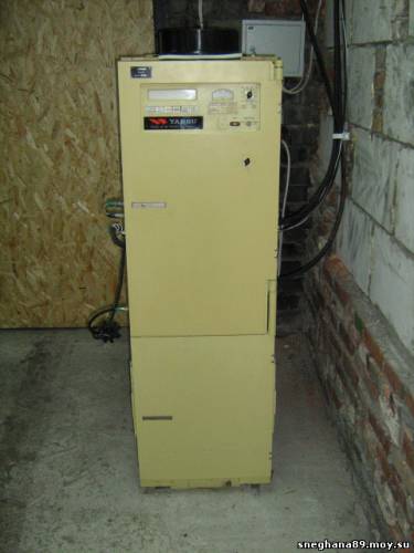
Radio amateurs know it for something else. Its power amplifier is a bank of GU-84B metal-ceramic tetrodes working in parallel into a broadband output system, so it can change frequency without the long mechanical tuning cycle of older transmitters. Hams who have one describe it as "an excellent amplifier for contests: it needs no retuning at all and the power is suitable," and, a little ruefully, "efficiency is low, of course: ten GU-84B tubes and only 10 kW" [SINGLE-SOURCE]. A Kharkiv ham photo album captions a yellow floor-standing cabinet as an R-631 and gives a 15 kW maximum with nine GU-84B tubes in the final [SINGLE-SOURCE]. That is the photograph at the top of this page, and its identification is [UNVERIFIED]; see "About the photograph."
This article explains how a parallel-tetrode broadband HF transmitter like the R-631 works, what the documented numbers say, where the sources disagree, and what the transmitter means to a ham with a big-gun streak.
SOURCES AND THEIR LIMITS
The R-631 is much less documented in open sources than the R-140 or the Vyaz-M2. No declassified technical description has surfaced online. This article rests on five kinds of source:
Defence catalogue entry. "Russia's Arms and Technologies," vol. XIII (naval C3), as transcribed by a European CIS-Navy monitoring site in 2008. It gives the R-631's role (surface ships), its exciter (Mayak-1), its wideband matching unit, range, continuous power, modes, cooling and maker [DOCUMENTED, but a second-hand transcription].
R-631-M1 specification, quoted by a former Border Guard ship radioman on a veterans' forum (2011). It describes the M1 as an improved version of "the prototype R-631" with about half the power consumption for the same antenna power, 20 % less mass, and gives a full specification table [SINGLE-SOURCE; the text reads like a manufacturer's brochure].
Ham photo album caption (sneghana89.moy.su, a Kharkiv radio-amateur site, uploaded 2010). It gives production from 1977 "to the present day," range, maximum power, tube line-up, anode voltage and current, dimensions and supply [SINGLE-SOURCE].
Ham forum posts on qrz.ru and a contest forum (ve3kf.build2.ru) about owning and operating Plamya amplifiers: ten GU-84B in parallel, about 10 kW, no retuning, 75 Ω output, a ninth-order low-pass filter on the output [SINGLE-SOURCE each].
Scientific mention. A qrz.ru poster cites a paper on the chirp (LChM) ionosonde transmitter complexes of the Institute of Solar-Terrestrial Physics (ISZF, Siberian Branch of the Russian Academy of Sciences), noting that "to improve electromagnetic compatibility, a ninth-order low-pass filter was installed at the output of the Plamya transmitter" [SINGLE-SOURCE, as quoted; the paper itself was not checked].
Where these disagree (and they do, on tube count and power), the disagreement is shown, not hidden.
ABOUT THE PHOTOGRAPH
The one photograph available for this article shows a tall, narrow, cream-yellow cabinet in a garage or outbuilding, with a small metered control panel at the top and a large plain lower door. The album caption identifies it as "Radio transmitter R-631 (Plamya)" and gives its height as 1.7 m and its width and depth as 0.7 m [SINGLE-SOURCE].
Identification: [UNVERIFIED]. There is no visible Cyrillic nameplate in the photograph, and no other photograph of an R-631 with a nameplate was found to compare it with. Points in its favour: the caption's specification matches the documented R-631 family (1.5–30 MHz, multi-kilowatt, 380 V three-phase), and the R-631-M1 power-amplifier rack is documented at 500 × 600 × 1,620 mm [SINGLE-SOURCE], close to the cabinet's proportions. Points against: none specific, except the absence of a nameplate.
The sticker. On the upper front panel is a small badge reading "YAESU," the Japanese amateur-radio brand. Yaesu never built anything like this cabinet. The badge appears to have been added after the fact, most likely by a ham radio operator who later owned or restored the unit, and it is not original equipment. The photograph is used as is; the badge should not be read as evidence of the cabinet's origin. [UNVERIFIED]
HISTORY AND MAKER
The Kharkiv album dates the start of R-631 production to 1977 and says it continued "to the present day" (that is, to 2010) [SINGLE-SOURCE]. The catalogue names the maker as the Russian Institute of High-Power Radio Engineering (OJSC, St Petersburg) [DOCUMENTED]. That institute is the post-Soviet form of VNIIMR, the Leningrad All-Union Research Institute of High-Power Radio Engineering, which also developed the 1961 Vyaz-M2 5 kW transmitter [BACKGROUND for the lineage; DOCUMENTED, factory history, that VNIIMR developed the Vyaz-M2]. So the R-631 is, in effect, the Vyaz-M2's naval grandchild from the same design house.
The R-631 belongs to a numbered family of Soviet naval HF transmitters. The catalogue also lists the R-635 for submarines (250 W continuous, up to 17 kW short-time with two PAs, also with the Mayak-1 exciter and an automatic wideband matching unit) and the later solid-state R-638 series made by "Neptun" [DOCUMENTED]. A Border Guard veteran on the same forum remembers three HF transmitters and one MF transmitter called "Plamya" R-630 on his patrol ship, 1 kW each, which "tuned in fractions of a second and were controlled remotely" from the ship's communications post [SINGLE-SOURCE]. So the name "Plamya" seems to have been used for a family (R-630, R-631) rather than one product [ESTIMATE].
The R-631-M1 came later. Its description calls the R-631 "the prototype" and claims "about half the power consumption at the same power delivered to the antenna, and 20 % less mass" [SINGLE-SOURCE]. It could be used with the Mayak-1, Artek-Sirius and Rodon exciters and was included in the communications complexes of first- and second-rank surface ships [SINGLE-SOURCE]. First and second rank cover cruisers, large destroyers and large anti-submarine ships, which tells us the R-631 family was a main-transmitter class item on major combatants [BACKGROUND for rank meaning].
SPECIFICATIONS AS DOCUMENTED
R-631, defence catalogue [DOCUMENTED, second-hand transcription]:
Role: shortwave transmitter for surface ships.
Includes: Mayak-1 exciter and wideband matching unit.
Frequency range: 1.5 to 30 MHz.
Output: 5.5 kW in continuous mode.
Modes: CW telegraphy; SSB and DSB AM telephony; 2FSK with shifts of 125, 200, 500 and 1,000 Hz; 2FSK with 15-fold frequency diversity in 2 kHz steps; PSK with 180° shift; PSK with 15-fold frequency diversity in 2 kHz steps; FM telephony.
Cooling: external forced air.
R-631, Kharkiv album caption [SINGLE-SOURCE]:
Production from 1977.
Range 1.5–30 MHz.
Output up to 15 kW.
Driver on a GU-84B; output stage nine GU-84B, common cathode.
Anode voltage 2,200 V; maximum anode current 15 A.
"Works with any type of antenna."
Height 1.7 m, width 0.7 m, depth 0.7 m.
Supply 380 V; maximum consumption 25 kW.
R-631-M1 [SINGLE-SOURCE]:
Range 1.5–30 MHz; emission classes A1A, H3E, J3E, F1B, G1B; frequency grid 100 Hz.
Output into 75 Ω: continuous 4.5 ± 1.5 kW; short-time 6.0 ± 2.0 kW.
Harmonic suppression: not less than 60 dB.
Maximum three-phase consumption: continuous 14.0 kW; short-time 16.0 kW.
PA rack: 500 × 600 × 1,620 mm, 350 kg.
Hams' reports [SINGLE-SOURCE each]: ten GU-84B in parallel; about 10 kW out; no retuning needed; output impedance close to 75 Ω, "certainly not 300 Ω"; ninth-order low-pass filter at the output.
RECONCILING THE NUMBERS
The figures above look contradictory at first: 5.5 kW, 10 kW, 15 kW. They are probably all describing the same kind of machine under different conditions [ESTIMATE for this whole section].
Continuous versus peak. The catalogue's 5.5 kW is continuous-mode power, the rating for key-down telegraph or FSK for hours. The M1's spec shows the pattern: 4.5 kW continuous and 6 kW short-time. Hams running SSB or contest CW care about peak power and short duty cycles; 10 kW PEP from a stage rated 5.5 kW continuous is plausible, especially if the operator pushes the anode current.
The 15 kW figure. The album gives 2,200 V and a maximum of 15 A anode current. That is 33 kW of DC input at maximum. At 45–50 % efficiency, typical of a broadband (untuned) parallel tetrode stage in linear service, that is about 15 kW output, so the 15 kW is the absolute peak the tube bank can make. But the same caption says maximum consumption is 25 kW from the mains, which is less than the 33 kW DC input at 15 A. So the 15 A must be a peak (or protection-trip) figure, not a continuous one. Treat 15 kW as a peak capability, not a rating.
Nine or ten tubes. The album says a GU-84B driver plus nine GU-84B in the output; the forum posts say ten GU-84B "in parallel." Ten tubes total (one driver plus nine finals) reconciles both.
Efficiency. The ham who called the efficiency "low" (10 kW from ten GU-84B) is right in the sense that a tuned class-C or class-B stage with a resonant tank would get more out of the same tubes. A broadband amplifier pays for its instant frequency changes with lower efficiency, because it cannot use a high-Q tank to restore a sine wave and recover energy. The M1's claim of half the consumption for the same output suggests the M1 redesign attacked exactly this weakness.
HOW THE R-631 WORKS — BLOCK DIAGRAM IN PROSE
No schematic of the R-631 is available. The description below combines the documented elements (exciter, GU-84B driver and parallel output stage, common cathode, 2.2 kV, wideband matching unit, ninth-order low-pass filter, 75 Ω output, no retuning) with how Soviet broadband naval transmitters of this generation were built [ESTIMATE unless marked].
1. Exciter (Mayak-1, or Artek-Sirius / Rodon on the M1). The exciter is a separate unit that generates the signal in every mode, on a synthesized grid (100 Hz on the M1) [DOCUMENTED that these exciters are used; SINGLE-SOURCE for 100 Hz]. It produces a low-level output, typically a fraction of a watt to a few watts, already in its final form: SSB, AM, FSK, PSK or keyed carrier. The R-631 is therefore a linear power amplifier chain behind a smart exciter, which is the modern way to build a transmitter and the reason the ham community thinks of the R-631 as "an amplifier" more than "a transmitter."
2. Driver — one GU-84B. The album states the driver is built on a GU-84B [SINGLE-SOURCE]. A single large tetrode as driver can supply tens to hundreds of watts of drive, which a bank of nine grid-driven tetrodes needs, because nine control grids in parallel present a low impedance and a large input capacitance.
3. Output stage — nine GU-84B in parallel, common cathode. The tubes are grid-driven (common cathode) [SINGLE-SOURCE], which gives high power gain. In parallel, their anodes are tied together, so the stage acts like one huge tetrode with nine times the current capability at the same voltage. At 2,200 V on the anodes, a low voltage for a multi-kilowatt stage, the stage's load impedance is low, which makes broadband matching to 75 Ω practical.
Why many smaller tubes in parallel instead of two very large ones, as in the Vyaz-M2? Three reasons stand out. First, lower anode voltage is safer and easier to insulate in a cramped, damp ship's compartment. Second, low impedance makes a broadband output possible. Third, the transmitter degrades gracefully: if one of nine tubes fails, the stage loses roughly a ninth of its power instead of going off the air, and on a ship at sea that matters more than efficiency.
4. Broadband output and the low-pass filter. The phrase "no retuning needed" [SINGLE-SOURCE] means the anode circuit is not a tuned tank. In broadband tube transmitters of this period, the anodes typically feed a wideband transmission-line or ferrite-loaded transformer that steps the low anode impedance up to 75 Ω. A broadband stage produces harmonics freely, so it must be followed by a switched bank of low-pass filters, one per sub-band (often about an octave each), to remove the second and third harmonics. The ISZF ionosonde paper's ninth-order low-pass filter [SINGLE-SOURCE] is exactly that kind of filter: a ninth-order LC ladder gives very steep cut-off. The M1's ≥60 dB harmonic suppression [SINGLE-SOURCE] is what a good filter bank achieves.
5. Wideband matching unit. The catalogue says the R-631 "includes a wideband matching unit" [DOCUMENTED]. On a ship, antennas are whips and wire antennas strung between masts, whose impedance varies wildly across 1.5–30 MHz. The matching unit transforms them to 75 Ω. On the submarine R-635, the catalogue specifies an "automatic wideband matching unit" [DOCUMENTED]; for the R-631 the word "automatic" is not given in the transcription.
6. Power supply. A 380 V three-phase supply [SINGLE-SOURCE] feeds a high-voltage rectifier for 2.2 kV anode, screen and bias supplies, and heater transformers for ten tubes. Ships use 380 V 50 Hz three-phase power in Soviet practice, so the transmitter plugs into the ship's main bus [BACKGROUND].
7. Cooling. "External forced air" [DOCUMENTED]: the transmitter takes cooling air from the ship's ventilation system or a separate blower and forces it through the anode radiators of the GU-84B bank.
THE GU-84B
The GU-84B (ГУ-84Б) is a Soviet metal-ceramic beam tetrode with forced-air cooling, used in HF and VHF power amplifiers [BACKGROUND]. Amateur sources treat it as a 2 kW-class tube: one GU-84B can make about 2 kW on 144 MHz in amateur designs, according to a qrz.ru thread on experience with the tube [SINGLE-SOURCE]. Published figures for heater voltage, anode dissipation and electrode voltages vary between sources, so builders should use the tube's own passport [ESTIMATE].
Nine of them at 2.2 kV in parallel, each running about a kilowatt of output at the lower voltage and conservative drive, gives the 5 to 10 kW figures reported [ESTIMATE].
The GU-84B is not used in the R-140, despite occasional claims to the contrary; the R-140 uses one GU-43B [DOCUMENTED; see the R-140 draft].
MODES IN PRACTICE
The catalogue's list of modes is a good guide to what a Soviet warship sent over HF [DOCUMENTED for the list; BACKGROUND for uses]:
CW: Morse, still the fallback mode for naval HF because it gets through when nothing else will.
SSB and DSB AM telephony: voice.
2FSK at 125, 200, 500, 1,000 Hz shift: teleprinter and data. The 200 Hz shift matches the Soviet naval broadcast standard monitored by Western listeners.
2FSK with 15-fold frequency diversity in 2 kHz steps: the same data sent on 15 frequencies spread over about 30 kHz, so that a fade or a jammer on one frequency does not stop the message. This is a robust anti-jamming and anti-fading technique.
PSK with 180° shift: binary phase shift keying, with and without the same 15-fold diversity.
FM telephony.
The M1's emission list (A1A, H3E, J3E, F1B, G1B) is the same set in ITU notation: CW, AM with full carrier on one sideband, SSB with suppressed carrier, FSK and PSK [SINGLE-SOURCE].
All of these are generated in the exciter, and the PA only has to amplify them linearly, which is why a broadband linear PA is the right architecture for this mode list.
SHIP INSTALLATION
On a first- or second-rank ship, the transmitter sits in a transmitter room (the "Peredayushchiy," the transmitting post), separated from the main communications post (KPS) where operators work [BACKGROUND; the Border Guard veteran mentions remote control "from the KPS" for the R-630, SINGLE-SOURCE]. Operators select frequency and mode remotely; the transmitter, exciter and matching units respond without anyone in the transmitter room. The veteran remembers older days, before such transmitters, when "sometimes I had to go to the transmitting post myself if the guys had trouble tuning" and that remote-controlled, instantly tuned transmitters made service "not life, but raspberries" (Russian slang for an easy life) [SINGLE-SOURCE].
A ship of this size would carry several HF transmitters for simultaneous links: ship-to-shore, the fleet broadcast, and inter-ship nets [BACKGROUND].
THE HAM ANGLE
Plamya as a contest amplifier. A Russian contest forum thread titled "Amplifier R-631 Plamya" calls it "an excellent PA for contests" because it "requires no retuning" [SINGLE-SOURCE]. In a contest, the operator jumps between bands constantly; a broadband amplifier that needs only a band-filter switch is ideal. The downside the same poster names is efficiency.
Output impedance. The same thread discusses whether the output is 300 Ω or 75 Ω; the conclusion is that it is "very close to 75 Ω, so most likely not 300 Ω but 75 Ω" [SINGLE-SOURCE], consistent with the M1's documented 75 Ω load [SINGLE-SOURCE].
Big-gun folklore. A qrz.ru poster jokes that ten GU-84B "easily put 15 to 20 kW into a dipole on the HF bands" and that "crows within 25 m of that dipole faint." The same thread mentions "information that hooligans broadcast on 160 m and around it with such a transmitter" [SINGLE-SOURCE]. That refers to illegal pirate broadcasting, not amateur practice.
Legal limits. In the US, amateurs are limited to 1,500 W PEP output; most countries are lower. An R-631 is useful to a ham only as a parts source (GU-84B tubes, sockets, broadband transformers, filters, high-voltage supply) or run far below its capability [BACKGROUND].
Practical issues. It needs 380 V three-phase and up to 25 kW [SINGLE-SOURCE]. It weighs several hundred kilograms (the M1's PA rack alone is 350 kg) [SINGLE-SOURCE]. Ten tubes' worth of heaters and blowers make it a noisy, hungry neighbour.
RESTORATION NOTES
[BACKGROUND, general practice]
Check every tube. A parallel stage hides weak tubes. Test each GU-84B's emission and look for gas before running them together. Mismatched tubes share current unequally; the strongest tube runs hottest.
Parasitic suppression. Nine paralleled tetrodes are prone to VHF parasitic oscillation because of the long anode bus. Keep the original suppressors and do not shorten or reroute the anode interconnections.
Filters. Never run the broadband PA without its low-pass filter bank in line. The harmonic output of an untuned stage would be illegal and damaging.
Air. The cabinet expects external forced air. In a garage installation, provide a blower and duct of adequate capacity and an airflow interlock.
Three phase. Do not run it from a phase converter of marginal capacity; the inrush of ten heaters and a big HV transformer is high.
COMPARISONS
Against the Vyaz-M2. Same design house, a generation apart. The Vyaz-M2 (1961) uses two large GU-5B triodes in a manually tuned push-pull resonant stage with a balanced output, AM/CW/FSK only. The R-631 (from 1977) uses ten GU-84B tetrodes in a broadband, low-voltage parallel stage behind a multi-mode synthesized exciter, and changes frequency quickly. See the Vyaz-M2 draft.
Against the R-140. The R-140 (1 kW, 1960s) uses one GU-43B in a tuned stage with a motor-driven 30–40 second autotune. The R-631 trades efficiency for near-instant band changes.
Against the R-631-M1. The M1 keeps the 1.5–30 MHz range and roughly the same continuous power but claims half the consumption and 20 % less mass [SINGLE-SOURCE], most likely through a more efficient output stage design [ESTIMATE].
Against later solid state. The R-638 series and the "Kompas" transmitter replaced tubes with transistors, with tuning times of 0.03 to 0.3 seconds and computer interfaces [DOCUMENTED, catalogue].
SOURCE CONFLICTS
Power: 5.5 kW continuous (catalogue), ~10 kW (ham), up to 15 kW (album). Reconciled above as continuous, typical peak and maximum peak [ESTIMATE].
Tube count: nine output plus one driver (album) vs ten in parallel (forum). Probably the same ten tubes.
Naming: "Plamya" is used for both R-630 (1 kW, per one veteran) and R-631 [SINGLE-SOURCE].
Photograph: identification [UNVERIFIED]; Yaesu badge appears to be a later addition, probably by a ham radio operator, not original equipment.
RELATED
R-140 — 1 kW SSB HF truck station with a single GU-43B and a motor-driven tuner.
Vyaz-M2 — 5 kW HF transmitter from the same design house, two GU-5B triodes in push-pull.
R-187 Azart — sixth-generation handheld radio.
R-173 Abzats — vehicle VHF FM set.
R-168 Akveduk — fifth-generation combined-arms radio family.
IN ONE SENTENCE
R-631 Plamya is the 1977-onward Russian naval HF transmitter, from the same St Petersburg design house as the Vyaz-M2, that drives a parallel bank of GU-84B tetrodes at 2.2 kV into a broadband 75 Ω output and filter bank behind a multi-mode Mayak-1 exciter, making about 5.5 kW continuous and well over 10 kW peak without retuning, which is why hams prize it as a contest amplifier.