WHAT IT IS
ZEVS (Russian: «ЗЕВС» or «Зевс», "Zeus"; often rendered in English-language forums as "3EBC" by reading the Cyrillic letters as Latin look-alikes) is the operational codename of the Russian Navy's 82 Hz extremely low frequency (ELF; in Russian military and radiophysical usage СНЧ, сверхнизкие частоты, or КНЧ, крайне низкие частоты) strategic submarine communications transmitter complex located on the Kola Peninsula (Кольский полуостров) in Murmansk Oblast, southeast of Murmansk and immediately south of the closed naval aviation garrison of Severomorsk-3 (Североморск-3). Built around the Soviet-developed «Вариация-1» (Variatsiya-1, "Variation-1") high-power ELF transmitting complex engineered by the Leningrad Komintern Scientific-Production Association (НПО им. Коминтерна, now the Russian Institute of High-Power Radio Engineering, ОАО «РИМР»), the facility consists of two spatially separated 2.5 MW radio-transmitting modules (5.0 MW total installed capacity when operated together in phase) situated roughly 10 to 11 km apart in a north-south line, each feeding a roughly 60 km east-west horizontal overhead transmission line grounded into the resistive Archean crystalline granite-gneiss bedrock of the Murmansk Block of the Fennoscandian (Baltic) Shield. [DOCUMENTED]
Its primary military mission is one-way strategic command and control: delivering encrypted "bell-ringer" alert calls and pre-formatted operational action codes from the Main Staff of the Russian Navy (Главный штаб ВМФ, ГШ ВМФ) and the General Staff of the Armed Forces of the Russian Federation (Генеральный штаб ВС РФ, ГШ ВС РФ) to nuclear-powered ballistic-missile submarines (РПКСН, ракетные подводные крейсера стратегического назначения, such as Project 667BDRM Delfin and Project 955/955A Borei / Borei-A) and multi-purpose or cruise-missile submarines (Project 885/885M Yasen, Project 949A Antey, Project 971 Shchuka-B) while they patrol at full operational keel depths of 100 to 400 metres and cruising speeds under the Arctic ice pack or in distant ocean basins. [DOCUMENTED]
Where conventional very-low-frequency (VLF, 14 to 25 kHz) shore stations such as Antey (RJH69 at Vileyka) or US Navy Cutler (NAA) suffer roughly 4.5 to 5.5 dB of seawater attenuation per metre of depth and therefore force a submarine either to rise near periscope depth or to stream a shallow buoyant wire or paravane buoy within 10 to 20 metres of the surface, an 82 Hz electromagnetic wave has a seawater skin depth of roughly 28 metres (an attenuation of only about 0.31 dB per metre). At the same time, an 82 Hz signal has a free-space wavelength of 3,656 kilometres—more than half the radius of the Earth—and propagates inside the spherical shell between the Earth's surface and the lower ionosphere as a single, virtually unattenuated transverse-magnetic waveguide mode (losing only 1.0 to 1.5 dB per 1,000 km), illuminating every ocean on Earth simultaneously from a single Kola Peninsula site. Since the United States Navy dismantled its twin 76 Hz ELF transmitters at Clam Lake, Wisconsin and Republic, Michigan in September 2004, ZEVS has stood alongside newer Chinese and Indian installations as the oldest and best-documented operational strategic ELF transmitter on Earth. [DOCUMENTED]
The open-source reconnaissance reality. Because ZEVS is a nuclear command-and-control installation of the highest strategic importance, virtually no official military manuals, architectural blueprints, or operational logs have ever been released by the Soviet or Russian Ministry of Defense. Almost everything known publicly about the physical layout of the transmitter compounds, the outdoor high-voltage transformer and series-capacitor tuning yards, the 60 km power-line corridors across the Kola forest-tundra, and the adjacent road network leading north to the Severomorsk-3 naval air base has been reconstructed from open-source satellite imagery, supplemented from the early 1990s onward by Russian Academy of Sciences (РАН) geophysical papers after Academician V. A. Kotelnikov and Academician E. P. Velikhov arranged for ZEVS to be used on a "dual-use" (двойное назначение) basis as a controlled-source electromagnetic sounder for probing the deep electrical conductivity of the Fennoscandian lithosphere and the upper ionosphere. [DOCUMENTED]
The one-paragraph version. To talk to a submerged submarine at hundreds of metres depth under Arctic sea ice, you must drop the radio frequency out of the kilohertz range down below 100 Hz, where salty seawater stops acting like an opaque mirror and lets the wave penetrate tens of metres per skin depth. At 82 Hz the wavelength is 3,656 km, so no mast or tower can radiate it. Instead, ZEVS uses the Earth's crust itself as part of a giant one-turn vertical magnetic loop: solid-state thyristor frequency converters fed from the Kola power grid pump 200 to 300 amperes of 82 Hz alternating current through a series-capacitor tuning bank into two parallel 60 km overhead transmission lines grounded at both ends in boggy electrode fields. Because the ancient Precambrian granite-gneiss under the Kola Peninsula is an exceptionally poor electrical conductor, the underground return current cannot hug the surface below the wire; it is forced 5 to 18 kilometres deep into the crust before rising to the far electrode, turning a 60 km wire and the rock beneath it into a radiating magnetic loop hundreds of square kilometres in cross-section. Even that continental-scale loop has an efficiency below one ten-thousandth of one percent—turning 2.5 megawatts of electrical input into barely one or two watts of radiated 82 Hz radio power—and the tiny bandwidth against global lightning noise limits throughput to a few bits per minute, taking 5 to 15 minutes just to deliver a three-letter code group telling a submarine to copy a preset operational directive or rise to receive a high-speed VLF or satellite transmission. [DOCUMENTED / ESTIMATE]
HOW TO READ THIS PAGE
Because official Soviet and Russian Navy documentation on ZEVS remains classified, every technical claim on this page carries an explicit source-quality label so the reader can tell primary scientific measurements and satellite observations apart from engineering calculations and unverified reports:
Scope and security note. Everything in this article is assembled strictly from open academic literature, published satellite imagery, and first-principles electromagnetics. ZEVS and the adjacent Severomorsk-3 garrison are active, restricted military installations of the Russian Federation's Northern Fleet, and nothing on this page is intended to assist anyone in approaching or interfering with them.
NAMES, DESIGNATIONS AND TERMINOLOGY: ZEVS, VARIATSIYA-1 AND SNCh
Russian military, industrial, and geophysical publications refer to the Kola Peninsula ELF facility and its frequency band under several distinct designations that are frequently conflated in English-language summaries.
| Term / Designation | Cyrillic / Expansion | Meaning and Context | Status |
| ZEVS / Zevs / "Zeus" / "3EBC" | «ЗЕВС» / «Зевс» (объект «Зевс») | The Soviet and Russian Navy operational codename for the Kola Peninsula 82 Hz ELF transmitter installation, named after Zeus, the sky and thunder god of Greek mythology—continuing the Soviet naval tradition of naming strategic VLF/ELF transmitters after classical mythological figures (Геркулес / Hercules, Антей / Antaeus, Атлант / Atlas, Прометей / Prometheus, Геракл / Heracles). The string "3EBC" seen in English forum posts is simply a visual transcription of the four Cyrillic letters З-Е-В-С using a Latin keyboard. | [DOCUMENTED] |
| Variatsiya-1 | «Вариация-1» (СНЧ-радиопередающий комплекс «Вариация-1») | The official industrial R&D codename (ОКР) and hardware designation of the 5,000 kW (2 × 2,500 kW) solid-state ELF radio-transmitting complex developed between 1975 and 1986 by NPO imeni Kominterna (ОАО «РИМР») and installed at Object ZEVS. While "ZEVS" is the naval facility and antenna complex as a whole, "Variatsiya-1" is the transmitting equipment complex inside the halls. | [DOCUMENTED] (ОАО «РИМР» historical chronicle; Vasilega) |
| SNCh vs. KNCh | СНЧ (сверхнизкие частоты) vs. КНЧ (крайне низкие частоты) | A major terminology trap between Russian and Western ITU standards. In modern ITU-R nomenclature, 3 to 30 Hz is ELF (КНЧ in literal translation) and 30 to 300 Hz is SLF (Super Low Frequency, СНЧ), though English engineering usage universally calls the entire 3 to 300 Hz submarine band ELF. In Soviet/Russian GOST and Navy terminology, 30 to 300 Hz is called СНЧ (сверхнизкие частоты, literally "super-low frequencies") and the wavelengths (10,000 to 1,000 km) are called СДВ or СНВ, whereas newer Russian space-physics papers translating English "ELF" back into Russian often write КНЧ (30 Hz to 3 kHz). Both СНЧ and КНЧ in Russian papers refer to ZEVS's 82 Hz band. | [DOCUMENTED] |
| Sinus / Energiya-1 / Energiya-2 | «Синус» / «Энергия-1» / «Энергия-2» | Not the main 2.5 MW ZEVS naval transmitters. These are smaller (20 to 200 kW) mobile or transportable thyristor ULF/ELF current generators built by the Kola Science Centre and partners for the civilian FENICS (Fennoscandian Electrical Conductivity from Soundings with Natural and Controlled Sources) experiments, which temporarily inject 0.1 to 200 Hz currents into decommissioned or industrial 100–120 km power lines on the Kola Peninsula. Secondary summaries occasionally confuse the 200 kW FENICS generators with the 2.5 MW ZEVS transmitters. | [DOCUMENTED] (Zhamaletdinov et al., 2015; Pilipenko et al., 2023) |
| Severomorsk-3 / Malyavr | Североморск-3 (посёлок / гарнизон Североморск-3, оз. Малъявр) | The closed military town and Northern Fleet naval air base located roughly 6 km north of the northern ZEVS station compound along the same north-south access road, about 28 km east-southeast of Murmansk. The ZEVS garrison support and the 2012 25th-anniversary publication for Object ZEVS are associated with Severomorsk-3. | [DOCUMENTED] |
| Murmansk Block | Мурманский блок (Балтийский / Фенноскандинавский кристаллический щит) | The Archean-age tectonic block of crystalline granite, plagiogranite, and gneiss occupying the northern coastal belt of the Kola Peninsula. Its extremely high electrical resistivity (104 to 105 Ω·m) is the geological prerequisite that allows the ZEVS horizontal ground dipoles to radiate. | [DOCUMENTED] (Velikhov et al., 1994; Zhamaletdinov, 2014) |
QUICK FACTS, WITH THE CONFLICTS SHOWN
| Parameter | Value / Specification | Source Label & Conflict Notes |
| Facility Codename | Object "ZEVS" (Объект «Зевс» / «ЗЕВС»); equipment complex «Вариация-1» (Variatsiya-1) | [DOCUMENTED] in RAS monographs and ОАО «РИМР» records. |
| Operator | Russian Navy (ВМФ России), Northern Fleet / Main Staff of the Navy Long-Range Operational Communications Directorate (Управление дальней оперативной связи ВМФ) | [DOCUMENTED] |
| Primary Developers | NPO im. Kominterna / ОАО «РИМР» (transmitter complex), NIIPT / НИИ постоянного тока (grounding electrodes & high-voltage power conversion), IZK / NIIF Leningrad State University (geoelectric siting & propagation), NIRFI (ionospheric physics) | [DOCUMENTED] (Zhamaletdinov, 2014; ОАО «РИМР») |
| Timeline | Concept & R&D late 1960s–1975; «Вариация-1» development 1975–1986; 1st module trial operation 1983; 2nd module completed 1985; state acceptance & combat duty (боевое дежурство) 1986 | [DOCUMENTED] (ОАО «РИМР»; Mol'kov, 2012) |
| Southern (Main) Transmitter Compound | 68.7157° N, 33.7069° E (68°42′59″ N, 33°42′28″ E in Russian literature), Kola Peninsula, ~33 km ESE of Murmansk | [DOCUMENTED] by satellite imagery and Russian geophysical coordinates. Contains the large L-shaped transmitter hall and outdoor step-down transformer / series-capacitor tuning yard. |
| Northern Transmitter Compound | 68.8135° N, 33.7538° E (68°48′48″ N, 33°45′06″ E in Russian literature), ~10.9 km NNE of the southern compound and ~6 km south of Severomorsk-3 airfield | [DOCUMENTED] by satellite imagery and Russian geophysical coordinates. |
| Eastern Grounding Terminals | Northern line eastern end: 68°46′44″ N, 35°09′06″ E (68.7789° N, 35.1517° E); Southern line eastern end: 68°42′04″ N, 35°12′52″ E (68.7011° N, 35.2144° E); array midpoint cited in geophysical papers as 68.7° N, 34.5° E (or 68°48′ N) | [DOCUMENTED]. Great-circle span from western modules to eastern grounding terminals is ~56.5 to 61.2 km; trace length along the overhead line corridors is ~60 km. |
| Antenna Configuration | Two parallel east-west horizontal grounded electric dipoles (HED / earth-return loops) built as 110 kV overhead power transmission lines (ЛЭП 110 кВ), each ~60 km long, separated north-to-south by ~10 km | [DOCUMENTED]. Note: one 2024 Russian conference abstract prints "1 km" separation by typographical error for "10 km"; satellite imagery, OpenStreetMap, and all other RAS papers confirm ~10 km north-south separation. |
| Nominal Naval Carrier Frequency | 82 Hz (free-space wavelength λ0 = 3,656.0 km; guided wavelength in Earth-ionosphere cavity λg ≈ 2,850 km) | [DOCUMENTED] |
| Modulation & Operational Bandwidth | Minimum-Shift Keying (MSK / phase-continuous FSK) within 81.0 to 83.3 Hz (e.g., 81.6 Hz and 82.7 Hz tones recorded in 2000); slow CW Morse on-off keying observed experimentally in the early 1990s | [DOCUMENTED] in Pilipenko et al. (2019), Russian literature, and European monitoring logs (Romero / vlf.it). |
| Geophysical Sounding Frequency Range | Stepped fixed frequencies from 30 Hz to 200 Hz (e.g., 32, 42, 64, 82, 128, 166, 188 Hz in 1990s crust-sounding sessions; broader 0.1 to 200 Hz range achieved with auxiliary mobile generators) | [DOCUMENTED] (Velikhov et al., 1994, 1998; Zhamaletdinov, 2014) |
| Installed Electrical Power | 2.5 MW per module (5.0 MW total when both modules run synchronously in phase) | [DOCUMENTED]. Conflict resolved: geophysical papers consistently cite "up to 2.5 MW" because typically only one module/antenna is driven at a time, whereas ОАО «РИМР» gives 2 × 2,500 kW = 5,000 kW for the full two-module «Вариация-1» complex. |
| Antenna Current | 200 to 300 A RMS at 82 Hz (falls at higher frequencies during geophysical sweeps; ~100–250 A typical in routine sessions) | [DOCUMENTED] (Velikhov et al., 1994; Pilipenko et al., 2019, 2024) |
| Actual Radiated ELF Power | Roughly 1.0 to 2.5 watts at 82 Hz per module (up to ~4–5 W with both modules in phase) | [ESTIMATE / DOCUMENTED order of magnitude]. More than 99.9999% of the 2.5 MW electrical input is dissipated as I2R heat in the 60 km aluminum-steel conductors, grounding grids, and deep crystalline bedrock. |
| Grounding Electrode Resistance | A few ohms (единицы Ом, ~2 to 4 Ω per grounding field), achieved via buried steel/conductor grids of ~1 km2 area at ~0.5 m depth plus contact boreholes in water-saturated basins | [DOCUMENTED] (NIIPT / Zhamaletdinov, 2014) |
| Data Rate | A few bits per minute (~0.03 to 0.15 bit/s); one 3-letter operational code group takes roughly 5 to 15 minutes to transmit depending on range and atmospheric noise | [ESTIMATE / SINGLE-SOURCE] (Friedman, 1997; Russian Wikipedia). Exact Russian naval coding and frame timing remain classified. |
STRATEGIC PURPOSE: WHY BALLISTIC-MISSILE SUBMARINES NEED AN 82 HZ BELL-RINGER
The strategic nuclear deterrent of the Soviet Union and the Russian Federation rests heavily on the survivability of its sea-based leg: the nuclear-powered ballistic-missile submarine fleet (РПКСН, ракетные подводные крейсера стратегического назначения) assigned to the Northern Fleet (based at Gadzhiyevo / Yagelnaya Bay on the Kola Peninsula) and the Pacific Fleet (based at Vilyuchinsk / Rybachiy on Kamchatka). In the late Cold War and modern Russian force structure, this fleet has encompassed the Project 667BDR Kalmar (Delta III), Project 667BDRM Delfin (Delta IV), Project 941 Akula (NATO Typhoon), and the current fourth-generation Project 955 and 955A Borei / Borei-A ballistic-missile submarines, alongside long-range cruise-missile and hunter-killer boats (Project 949A Antey / Oscar II, Project 971 Shchuka-B / Akula, and Project 885/885M Yasen / Yasen-M). [DOCUMENTED / BACKGROUND]
A strategic submarine on deterrent patrol has a single overriding rule: remain undetected. Its acoustic, magnetic, hydrodynamic, thermal, and visual signatures are lowest when it cruises slowly at substantial keel depth—typically 100 to 300 metres or more in open ocean, or beneath the thick multi-year pack ice of the Arctic Basin and the Barents/Kara bastion—well below the surface thermocline layer where sound channels trap hull noise and far below the effective range of airborne Magnetic Anomaly Detection (MAD) sensors, synthetic-aperture radar (SAR) wake detectors, and optical/infrared satellites. [BACKGROUND]
The VLF depth trap. Throughout the 1950s and 1960s, both the Soviet Navy and the United States Navy built massive 1,000 to 2,000 kW shore stations in the very-low-frequency band (VLF, 14 to 25 kHz), including the Soviet stations at Nizhny Novgorod (Goliath), Khabarovsk (Hercules), Vileyka (Antey), Arkhangelsk (Atlant), Bishkek (Prometey), and Krasnodar (Gerakl). VLF waves propagate reliably around the globe in the Earth-ionosphere waveguide at 50 to 200 bits per second, fast enough to carry encrypted teleprinter messages. However, at 18 to 25 kHz, the electromagnetic skin depth in seawater (conductivity σ ≈ 4 S/m) is only 1.6 to 1.9 metres, corresponding to an exponential attenuation of 4.6 to 5.5 dB for every single metre of depth. By the time a 20 kHz signal reaches 20 metres below the sea surface, it has lost roughly 100 dB (a factor of ten billion in power); by 40 metres it has lost 200 dB and lies hopelessly below the thermal noise of any receiver. [ESTIMATE / DOCUMENTED]
To copy a VLF broadcast continuously or on a scheduled clock window, a submarine must do one of two things, both of which carry severe tactical penalties:
How 82 Hz ELF breaks the depth constraint. Because seawater skin depth scales inversely with the square root of frequency (δ = √(2 / ωμσ)), dropping the carrier frequency by a factor of 250—from ~20,500 Hz (VLF) down to 82 Hz (ELF)—increases the seawater skin depth by a factor of √250 ≈ 15.8, from 1.76 metres to 27.8 metres (in 4 S/m temperate ocean water) and up to 32 to 34 metres in colder, slightly less conductive Arctic water (σ ≈ 2.7 to 3.0 S/m). The vertical attenuation rate drops from ~5.0 dB/m at VLF to just 0.26 to 0.31 dB/m at 82 Hz. At a keel depth of 100 metres, an 82 Hz signal has suffered only ~26 to 31 dB of seawater loss—less than a 20 kHz VLF signal suffers at just 6 metres depth! Even at 300 to 400 metres depth, the cumulative seawater loss at 82 Hz is roughly 80 to 125 dB, within the link margin of a sensitive towed ELF antenna and a narrowband correlation receiver integrating over several minutes. [ESTIMATE / DOCUMENTED]
The operational concept: "bell-ringer" and pre-formatted action codes. What ELF gains in depth penetration and global propagation, it pays for in bandwidth. With a carrier frequency of only 82 Hz and a usable modulation span of roughly 1 to 2.3 Hz (81.0 to 83.3 Hz), ZEVS cannot transmit free-text operational orders or targeting coordinates in real time. Instead, it operates in two complementary modes within the Russian Navy's layered command-and-control architecture (see Russian C3 and Kazbek):
SATELLITE IMAGERY ANALYSIS, SITE GEOGRAPHY AND REGIONAL MILITARY CONTEXT (SEVEROMORSK-3)
As noted at the top of this article, because Object ZEVS is an active strategic nuclear C3 installation, the Russian Ministry of Defense publishes no facility maps or equipment photographs. Open-source satellite imagery, combined with the geographic coordinates published in Russian Academy of Sciences crust-sounding papers, provides nearly all of our concrete visual knowledge of the ground infrastructure.
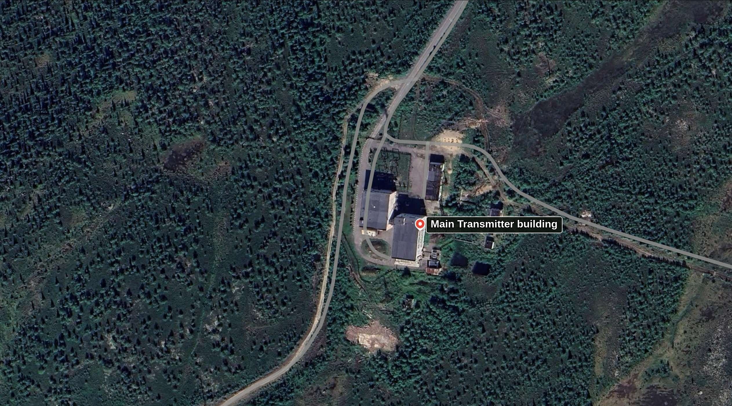
1. The Southern (Main) Transmitter Compound (68.7157° N, 33.7069° E / 68°42′59″ N, 33°42′28″ E). The first satellite image near the top of this page (zevs1.jpg), captured from Google Maps satellite imagery (Airbus / Maxar Technologies) by the site owner and annotated with the plain text label "Main Transmitter building", shows the southern ZEVS transmitting compound in detail. Sitting in a cleared gravel and bedrock perimeter carved out of the coniferous Kola taiga roughly 33 km east-southeast of Murmansk, the compound displays the unmistakable signature of a megawatt-class ELF power-conversion and resonant-tuning plant:
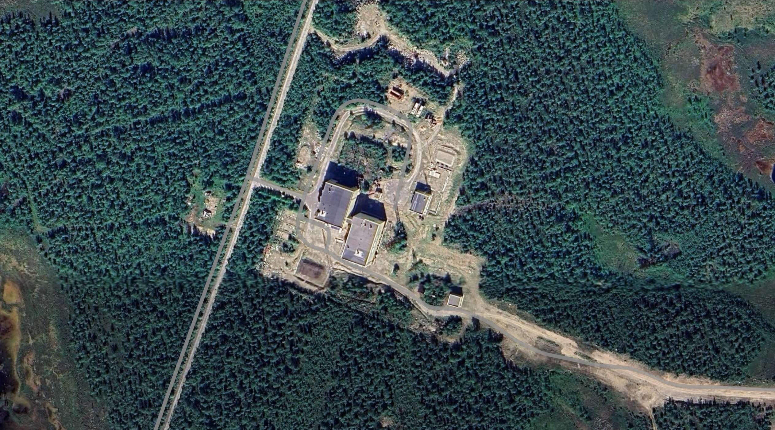
2. The Northern ZEVS Station Compound (68.8135° N, 33.7538° E / 68°48′48″ N, 33°45′06″ E). Roughly 10.9 km north-northeast of the main southern transmitter compound, along the same paved north-south military highway, lies the second ZEVS station compound, shown in the second satellite image above (zevs2.jpg), also extracted from Google Maps imagery provided by the site owner.
68°48′48″ N, 33°45′06″ E (this northern site) and 68°42′59″ N, 33°42′28″ E (the southern site), feeding the northern ~60 km antenna line (ending at 68°46′44″ N, 35°09′06″ E) and the southern ~60 km antenna line (ending at 68°42′04″ N, 35°12′52″ E). Notably, in satellite imagery the southern compound displays a more prominent outdoor transformer/capacitor switchyard immediately north of its main hall, whereas the northern compound has a cleaner exterior yard layout with smaller enclosed switching structures and a gravelled southern corridor leading east into the tundra. Whether the southern compound currently serves as the primary grid-entry and power-conversion hub or whether the northern module houses more of its matching gear under roof is not stated in open sources. [DOCUMENTED for coordinates and dual-module role; UNVERIFIED for internal equipment split]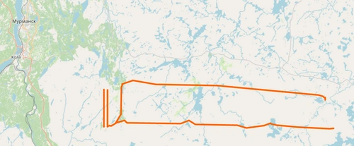
3. The 60 km Ground-Dipole Corridors and Road Network (zevs3.webp). The third image above shows the full geographic footprint of the ZEVS antenna system plotted in orange across the Kola Peninsula east of Murmansk (Мурманск) and Kola (Кола) on the Kola Bay (Кольский залив):
4. Regional Military Context: Severomorsk-3 Naval Air Base and the Kola Strategic Bastion. ZEVS does not sit in an unprotected civilian wilderness; it sits deep inside the most heavily fortified naval and air-defense exclusion zone in the Russian Arctic. If you follow the straight north-south military road northward from the southern ZEVS main transmitter building (68.7157° N) past the northern ZEVS station compound (68.8135° N) for just 6 kilometres, the road arrives directly at the closed garrison and concrete runway of Severomorsk-3 (Североморск-3, also known historically as Malyavr after adjacent Lake Malyavr, centered near 68.866° N, 33.715° E). [DOCUMENTED]
On satellite imagery of Severomorsk-3, following the access road north from ZEVS reveals a full-scale military airfield with a 2,500-metre concrete runway, taxiway loops, dispersed concrete hardstands, and revetted aircraft shelters where twin-tailed, swept-wing heavy fighters of the Sukhoi Su-27 / Su-33 / Su-35 Flanker family sit parked in the open alongside smaller twin-tailed aircraft and naval helicopters:
DEVELOPMENT AND OPERATIONAL HISTORY (1959–PRESENT)
1959–1970: From Christofilos's ground dipole to the Soviet Navy requirement. The physical concept of using a multi-kilometre overhead wire grounded at both ends into low-conductivity Precambrian bedrock to form an earth-return ELF loop was first proposed in 1958–1959 by Greek-American physicist Nicholas Christofilos for the US Navy (leading to Project Sanguine, Project Seafarer, and eventually the 76 Hz US ELF system). As the Soviet Navy commissioned its second-generation Project 667A Navaga (Yankee) and long-range Delta-class (Project 667B/BD/BDR) SSBNs in the late 1960s and early 1970s—capable of launching intercontinental ballistic missiles from patrol bastions beneath the Arctic ice cap without transiting the NATO-monitored GIUK gap—the Navy's Communications Directorate faced an acute operational requirement: reach submerged missile submarines at depths of 100+ metres anywhere on Earth, especially under polar ice where VLF buoys could not survive. [DOCUMENTED (Zhamaletdinov, 2014)]
Early 1970s: The Leningrad / Kola scientific-industrial consortium. Designing an ELF transmitter from scratch required solving problems that crossed radio engineering, high-voltage power transmission, and solid-earth geophysics. A multi-institute Soviet consortium was assembled under the Navy's Long-Range Operational Communications Directorate (Управление дальней связи ВМФ):
1975–1986: Construction of «Вариация-1» and entry into combat service. According to the official historical chronicle of ОАО «РИМР», engineering development and site construction of the two-module «Вариация-1» ELF complex ran from 1975 to 1986. The first 2,500 kW transmitting module was placed into experimental operation in 1983; construction of the second 2,500 kW module and its second 60 km antenna line was completed in 1985; and in 1986 the complete 5,000 kW complex was formally accepted into service by the USSR Navy and placed on permanent combat duty (боевое дежурство) as Object "ZEVS". [DOCUMENTED]
1990: Global field strength verification and the 10 dB advantage over US ELF. Although ZEVS was built under strict Soviet secrecy, an 82 Hz transmitter radiating into the global Earth-ionosphere waveguide cannot hide its signal once turned on. By the late 1980s and 1990, Western researchers (including Stanford University's STAR Laboratory under Antony Fraser-Smith and Peter Bannister, using sensitive ELF/ULF induction-coil magnetometers deployed globally, including at Arrival Heights in Antarctica and Sondrestromfjord in Greenland) were regularly recording strong, frequency-modulated 82 Hz signals originating from the Kola Peninsula. As noted in the 2014 Kola Science Centre monograph and Russian Wikipedia, comparative analysis of 1990 global ocean and Antarctic measurements showed that the 82 Hz signal from ZEVS was approximately 10 dB stronger (roughly ten times higher in received power, or three times higher in field amplitude) at long range than the 76 Hz signal from the US Navy's dual Wisconsin/Michigan ELF system. [DOCUMENTED]
1991–2014: Post-Soviet declassification of the signal and "dual-use" geophysical sounding. Following the dissolution of the USSR, Russian geophysicists pointed out that since Western intelligence services and university magnetometers were already recording every ZEVS transmission worldwide and reconnaissance satellites had photographed the 60 km power lines in detail, keeping the existence of the 82 Hz source secret from Russian scientists was pointless. Supported by Academician V. A. Kotelnikov (chairman of the RAS Scientific Council on Radiophysical Methods of Studying Seas and Oceans) and Academician E. P. Velikhov, the Russian Navy agreed in the early 1990s to operate ZEVS on a "binary" or dual-use (двойное назначение) schedule: between naval traffic sessions, the transmitter was stepped across discrete frequencies from 30 to 200 Hz while geophysical teams across Fennoscandia, Karelia, Finland, and Svalbard recorded the electromagnetic field to map the deep electrical structure of the lithosphere down to 100–200 km depth. The landmark first paper by E. P. Velikhov, A. A. Zhamaletdinov, L. A. Sobchakov, A. V. Veshev, A. K. Saraev, A. D. Tokarev et al. was published in Doklady Akademii Nauk in 1994 (Vol. 338, No. 1, pp. 106–109), and two decades of ZEVS scientific research were collected in a two-volume 2014 monograph published by the Kola Science Centre in Apatity. [DOCUMENTED]
2000s–2026: Modern multi-band expansion and satellite detection. In the 2000s, European VLF/ELF hobbyists (notably Renato Romero in Cumiana, Italy, documented on vlf.it) recorded ZEVS's 82 Hz MSK transmissions shifting between 81.6 Hz and 82.7 Hz over multi-minute intervals. According to A. V. Mol'kov's 2012 Severomorsk-3 publication marking 25 years of ZEVS operations, by 2012 the facility had evolved into a broader naval transmitting complex spanning multiple bands from UHF to VLF/ELF, supporting command of Northern Fleet forces alongside its core deep-submarine ELF mission. Most recently, between 2019 and 2025, space physicists at the Institute of Physics of the Earth (ИФЗ РАН) and Space Research Institute (ИКИ РАН) published detailed analyses of ZEVS 82 Hz waves leaking upward through the ionosphere into low Earth orbit, recorded at 660 km altitude by the French DEMETER satellite and at ~500 km altitude by the Chinese-Italian CSES-01 satellite during 2022 overflights of the Kola Peninsula and White Sea—confirming that ZEVS remains in active operational service. [DOCUMENTED]
THE PHYSICS OF ELF PROPAGATION: SEAWATER SKIN DEPTH AND THE EARTH–IONOSPHERE WAVEGUIDE
To understand why the Soviet Navy built two 60 km power lines across the Kola tundra to radiate barely two watts of 82 Hz electromagnetic energy, we have to walk through two pieces of classical electrodynamics: (1) how an electromagnetic wave penetrates a conducting medium like ocean water, and (2) how an electromagnetic wave whose wavelength is longer than 3,600 km travels around a spherical Earth. Every equation below is standard Maxwell physics, and the worked numbers are labelled [ESTIMATE] where they apply textbook formulas to ZEVS's published 82 Hz parameters.
1. Maxwell's equations in seawater and the skin-depth law. Inside ocean water of electrical conductivity σ (measured in siemens per metre, S/m), relative permittivity εr ≈ 80, and magnetic permeability μ ≈ μ0 = 4π × 10-7 H/m, Ampère's circuital law for a time-harmonic wave at angular frequency ω = 2πf reads:
∇ × H = (σ + jωεrε0) E
The ratio of the conduction current density (σE, carried by dissolved sodium and chloride ions) to the displacement current density (ωεrε0E) at f = 82 Hz (ω = 2π × 82 ≈ 515.22 rad/s) in typical temperate seawater (σ = 4.0 S/m) is:
σ / (ω εr ε0) = 4.0 / (515.22 × 80 × 8.854 × 10-12) ≈ 1.096 × 10⁷
Because conduction current outweighs displacement current by more than ten million to one, seawater at 82 Hz behaves as an overwhelmingly good conductor. The wave equation inside the water simplifies to a diffusion-wave equation with complex propagation constant γ = α + jβ = √(jωμ0σ) = (1 + j) √(ωμ0σ / 2). The real and imaginary parts are equal, and their reciprocal defines the electromagnetic skin depth (толщина скин-слоя, δ)—the vertical distance over which the electric and magnetic field amplitudes fall to 1/e ≈ 0.3679 of their surface value (an attenuation of 20 log10(e) = 8.6859 dB):
δ = √(2 / (ω μ0 σ)) = 1 / √(π f μ0 σ) ≈ 503.29 / √(σ · f) [metres]
Let us plug f = 82 Hz into this formula for two realistic ocean environments [ESTIMATE]:
δ = 503.29 / √(4.0 × 82) = 503.29 / √328 = 503.29 / 18.111 = 27.79 metres. The vertical attenuation rate is αdB = 8.6859 / 27.79 = 0.3126 dB per metre. Inside the water, the wavelength is compressed from 3,656 km in air down to λsea = 2πδ = 174.6 metres, and the phase velocity slows from 300,000 km/s in air to vsea = ωδ = 515.22 × 27.79 = 14,318 m/s (just 14.3 km/s!).δ = 503.29 / √(3.0 × 82) = 503.29 / 15.684 = 32.09 metres, cutting the vertical attenuation rate to just 0.2707 dB per metre. At 100 metres depth under the Arctic ice cap, the seawater loss at 82 Hz is only 27.1 dB.
2. Snell's law at the sea surface: why the wave bends straight down. In the air above the ocean, the 82 Hz wave travels horizontally along the Earth's surface at vph ≈ 0.78c ≈ 2.34 × 10⁸ m/s. Inside the ocean, the wave speed is vsea ≈ 1.43 × 10⁴ m/s. The magnitude of the refractive index jump at the air-water interface is therefore enormous—roughly 2.34 × 10⁸ / 1.43 × 10⁴ ≈ 16,300. By Snell's law of refraction (sin θsea = (vsea / vair) sin θair), even a grazing wave skimming horizontally along the ocean surface (sin θair ≈ 1) is refracted inside the water to within 0.0035 degrees of the vertical! Regardless of where the submarine is relative to the Kola Peninsula, the 82 Hz wave enters the sea surface and propagates straight downward toward the ocean floor as a horizontally polarized plane wave, with its horizontal magnetic field Hh aligned perpendicular to the great-circle bearing from ZEVS and its horizontal electric field Eh aligned along the great-circle bearing from ZEVS. [DOCUMENTED / BACKGROUND]
Moreover, at the air-sea boundary the tangential horizontal magnetic field Hh is continuous across the surface, and inside the water the downward-travelling horizontal electric field Ew(z) and horizontal magnetic flux density Bw(z) = μ0Hh(z) are locked together by the intrinsic wave impedance of seawater, |ηsea| = √(ωμ0 / σ):
|ηsea| = √((515.22 × 4π × 10-7) / 4.0) = √(1.6186 × 10⁻⁴) = 0.01272 Ω (|Ew| / |Bw| = √(ω / (μ0σ)) ≈ 0.359 (μV/m) per pT)
That simple ratio—roughly 0.36 microvolts per metre of underwater horizontal electric field for every 1 picotesla of underwater horizontal magnetic field at 82 Hz—governs how submarine receiving antennas work, as we will see in the submarine hardware section below. [ESTIMATE]
3. Frequency-by-frequency seawater attenuation comparison. The table below compares ZEVS at 82 Hz against the US 76 Hz ELF system, the Russian Alpha (RSDN-20) VLF navigation chain, the Russian Navy VLF broadcast network (Antey / RDL), the US Navy Cutler VLF station, Chayka (100 kHz LF), and shortwave HF across realistic submarine operating depths in standard σ = 4.0 S/m seawater [ESTIMATE]:
| System & Frequency | Free-Space Wavelength λ0 | Skin Depth δ (4 S/m) | Loss Rate (dB/m) | Loss at 15 m | Loss at 50 m | Loss at 100 m | Loss at 250 m | Loss at 400 m |
| 76 Hz (US Navy ELF, Clam Lake / Republic) | 3,944.6 km | 28.87 m | 0.301 dB/m | 4.5 dB | 15.0 dB | 30.1 dB | 75.2 dB | 120.3 dB |
| 82 Hz (Russian Navy ZEVS, Kola Peninsula) | 3,656.0 km | 27.79 m (32.1 m in 3 S/m Arctic) | 0.313 dB/m (0.271 dB/m in Arctic) | 4.7 dB | 15.6 dB | 31.3 dB (27.1 dB in Arctic) | 78.1 dB (67.7 dB in Arctic) | 125.0 dB (108.3 dB in Arctic) |
| 200 Hz (ZEVS upper crust-sounding limit) | 1,499.0 km | 17.79 m | 0.488 dB/m | 7.3 dB | 24.4 dB | 48.8 dB | 122.0 dB | 195.3 dB |
| 12.65 kHz (Alpha RSDN-20 VLF navigation) | 23.70 km | 2.24 m | 3.88 dB/m | 58.2 dB | 194.1 dB (unusable) | 388 dB | >900 dB | hopeless |
| 18.1 kHz (Russian Navy RDL VLF broadcast) | 16.56 km | 1.87 m | 4.64 dB/m | 69.7 dB | 232.2 dB (unusable) | 464 dB | >1,100 dB | hopeless |
| 20.5 kHz (Antey RJH69 Beta lowest slot) | 14.62 km | 1.76 m | 4.94 dB/m | 74.1 dB | 247.1 dB (unusable) | 494 dB | >1,200 dB | hopeless |
| 24.0 kHz (US Navy Cutler NAA VLF) | 12.49 km | 1.62 m | 5.35 dB/m | 80.2 dB | 267.4 dB (unusable) | 535 dB | >1,300 dB | hopeless |
| 100 kHz (Chayka / LORAN-C LF) | 3.00 km | 0.80 m | 10.91 dB/m | 163.7 dB | 545 dB | >1,000 dB | hopeless | hopeless |
| 3.0 MHz (Shortwave HF) | 100.0 m | 0.145 m | 59.8 dB/m | 897 dB | hopeless | hopeless | hopeless | hopeless |
Look closely at the 15-metre and 250-metre columns in the table above. An 82 Hz signal from ZEVS at a submarine depth of 250 metres suffers roughly the same seawater attenuation (68 to 78 dB) as a 20.5 kHz VLF signal from Antey suffers at just 15 metres depth! That is why an ELF receiver antenna can stay rigged directly along or just behind the submarine's hull at full patrol depth, whereas a VLF antenna must always be floated or planed up into the top 15 to 20 metres of the ocean. [ESTIMATE]
4. Propagation in the Earth–Ionosphere Spherical Waveguide. Once radiated into the atmosphere, how does an 82 Hz wave reach the South Atlantic, the Pacific, or the Arctic Basin? The conducting surface of the Earth (land and ocean) and the lower boundary of the ionosphere (the daytime D-region at h0 ≈ 60–70 km and the nighttime E-region at h ≈ 80–90 km) form a spherical concentric-shell waveguide around the planet.
In any parallel-plate or spherical waveguide of height h, all transverse-electric (TEn) and higher-order transverse-magnetic (TMn, n ≥ 1) modes have a cutoff frequency given by fc,n = n · c / (2h). For h = 75 km, the first higher-order cutoff is at fc,1 = 300,000 / 150 = 2,000 Hz (2 kHz). At 20 kHz (VLF), the waveguide is 5 wavelengths tall and supports roughly ten simultaneous modes that beat against one another, creating deep modal interference nulls at certain distances and sharp phase jumps across the day-night sunrise/sunset terminator.
At 82 Hz, by contrast, the waveguide height (h ≈ 75 km) is only one fiftieth of a wavelength (h / λ0 ≈ 75 / 3,656 ≈ 0.0205), and the operating frequency lies a factor of 24 below the first waveguide cutoff! As a result (first worked out rigorously by James R. Wait, 1970, 1977, and in Russian by L. A. Sobchakov, E. D. Tereshchenko, and A. P. Nickolaenko):
Er, stretching straight from the ground to the ionosphere like the field between the plates of a spherical capacitor), the magnetic field is horizontal and transverse to the propagation path (Hφ), and a small forward "wave tilt" at the imperfectly conducting sea surface produces the horizontal electric field (Eθ = ηsea Hφ) that couples into the ocean. Because only one mode exists, there is no multi-mode fading anywhere on Earth until the signal approaches the antipode. [DOCUMENTED / BACKGROUND]S = c / vph − j αwg has a real part Re(S) ≈ √(hm / he) ≈ 1.22 to 1.33. Consequently, the phase velocity of ZEVS's 82 Hz wave in the waveguide is vph ≈ 0.75c to 0.82c (225,000 to 246,000 km/s), and the actual guided wavelength along the Earth's surface is compressed from 3,656 km to λg ≈ 2,750 to 3,000 km. [DOCUMENTED / ESTIMATE]1/r (cylindrical spreading). On a sphere of radius RE = 6,371 km, waves expanding outward from the Kola Peninsula spread over circumferences proportional to sin(d / RE). Beyond d = πRE/2 ≈ 10,000 km (the equator relative to the transmitter), the great-circle paths begin re-converging toward the antipode of ZEVS (located in the Southern Ocean near Antarctica at 68.7° S, 145.5° W), so geometric spreading actually reverses and boosts field strength between 12,000 and 19,000 km! That is why US researchers in 1990 easily recorded ZEVS at Arrival Heights, Antarctica (~16,500 km from Murmansk). [DOCUMENTED]HOW A HORIZONTAL GROUND-DIPOLE ANTENNA WORKS AND WHY THE KOLA CRUST IS ESSENTIAL
If you ask a radio engineer to build an antenna for a wavelength of λ0 = 3,656 km, his first instinct—a vertical monopole tower or umbrella like Antey—is physically impossible. Let us see why in two lines of arithmetic [ESTIMATE]:
Suppose you tried to feed Antey's 305-metre umbrella (effective height heff ≈ 200 m, static capacitance C0 ≈ 0.3 μF for all three umbrellas combined) at 82 Hz. Its radiation resistance would be Rrad = 160π2(heff / λ0)2 = 1,579 × (200 / 3,656,000)2 = 4.7 micro-ohms (4.7 × 10⁻⁶ Ω), while its capacitive reactance would be XC = 1 / (2π × 82 × 0.3 × 10-6) = 6,469 Ω. Even to radiate a pitiful 0.01 watts of 82 Hz power, you would need an antenna current of I = √(0.01 / 4.7 × 10⁻⁶) = 1,458 A, which across 6,469 Ω of capacitive reactance produces a terminal voltage of V = I · XC = 9.43 million volts (9.43 MV RMS)! No insulator or helix coil on Earth can hold off 9.4 megavolts in open air without flashing over into a giant lightning arc.
1. The Horizontal Electric Dipole (HED) / Earth-Return Loop Principle. Because a short open-ended capacitor antenna requires impossible megavolts at 82 Hz, an ELF transmitter must instead use a closed current loop—an inductive antenna in which hundreds of amperes can circulate at manageable kilovolt potentials. Building a vertical wire loop tens of kilometres tall in the air is impossible, so Nicholas Christofilos (1959) and his Soviet counterparts turned the loop upside down and buried its bottom half inside the Earth's crust:
2. Why ordinary soil ruins the antenna—and why resistive Precambrian granite makes it work. Here we hit the single most important physical insight of the entire ZEVS project. In the overhead wire, current +I flows from West to East. Underground, the return current −I flows in the opposite direction, from East to West. If the underground return current flowed right along the surface just a few metres beneath the overhead wire, the magnetic field of the underground current −I would be equal and opposite to the magnetic field of the overhead wire +I, and the two would cancel each other out!
How deep does the alternating return current actually flow in the Earth? By the exact same skin-depth law we used for seawater! In homogeneous rock of electrical conductivity σg (or resistivity ρg = 1 / σg in Ω·m), alternating earth-return current at frequency f diffuses downward to a characteristic crustal skin depth (глубина скин-слоя в земной коре):
δcrust = √(2 / (ω μ0 σg)) = 503.29 × √(ρg / f) [metres]
As shown by Carson (1926), Wait (1972), and Sobchakov / Zhamaletdinov (1994, 2014), a horizontal wire of length L carrying current I over a homogeneous earth of skin depth δcrust radiates identically to a vertical one-turn rectangular magnetic loop antenna of length L and effective vertical height (current return depth):
heff = δcrust / √2 ≈ 0.7071 · δcrust = 355.88 × √(ρg / f) [metres]
with an effective radiating loop area Aeff = L · heff = L · δcrust / √2 and an effective horizontal magnetic dipole moment Mm = I · Aeff = I · L · δcrust / √2 (in A·m2). Because radiated power is proportional to the square of the dipole moment (Prad ∝ Mm2 ∝ I2 L2 δcrust2 ∝ I2 L2 ρg), the radiated power of an ELF ground dipole is directly proportional to the electrical resistivity ρg of the deep bedrock beneath the antenna! [DOCUMENTED]
Notice the fascinating reversal between VLF and ELF siting requirements:
Aeff = L · heff of the subterranean loop! (Only at the two terminal points where the electrodes touch the ground do you want local surface moisture to reduce contact resistance.)Let us compare what happens to a 60 km, 300 A, 82 Hz dipole over three different geological terrains [ESTIMATE, using published Murmansk Block resistivities from Velikhov et al., 1994 and Pilipenko et al., 2025]:
| Geological Substrate | Resistivity ρg (Conductivity σg) | 82 Hz Crustal Skin Depth δcrust | Effective Return Depth heff = δ/√2 | Effective Loop Area Aeff (for L = 60 km) | Magnetic Moment Mm (at I = 300 A) | Relative Radiated Power |
| Ordinary wet soil / sedimentary basin (e.g., Central Russian Plain) | 100 Ω·m (10-2 S/m) | 555.8 m (0.56 km) | 393 m (0.39 km) | 23.6 km2 | 7.07 × 10⁹ A·m2 | 1× (baseline—uselessly weak) |
| Laurentian Shield granite/gabbro (US ELF, Wisconsin / Michigan average) | ~3,200 to 5,000 Ω·m (2–3 × 10⁻⁴ S/m) | 3.14 to 3.93 km | 2.22 to 2.78 km | 133 to 167 km2 (per 60 km) | 4.0 to 5.0 × 10¹⁰ A·m2 | 32× to 50× stronger |
| Murmansk Block Archean granite-gneiss (ZEVS, conservative upper-crust average) | 10,000 Ω·m (10-4 S/m) | 5.56 km | 3.93 km | 235.8 km2 | 7.07 × 10¹⁰ A·m2 | 100× stronger (+20 dB) |
| Murmansk Block dry crystalline core (ZEVS, peak resistivity reported by Pilipenko et al., 2025 & Zhamaletdinov, 2014) | 30,000 to 100,000 Ω·m (3.3 × 10⁻⁵ to 10-5 S/m) | 9.63 to 17.58 km | 6.81 to 12.43 km | 408.4 to 745.7 km2 | 1.23 to 2.24 × 10¹¹ A·m2 | 300× to 1,000× stronger (+25 to +30 dB) |
That table explains both why ZEVS had to be built on the Murmansk Block of the Kola Peninsula and why US Navy researchers in 1990 measured ZEVS's 82 Hz signal as roughly 10 dB stronger worldwide than the US 76 Hz ELF system:
3. Worked calculation: Radiation resistance, total radiated ELF power, and distant field strength [ESTIMATE]. Using James R. Wait's standard excitation formula for a horizontal electric dipole of length L over a homogeneous earth of conductivity σg radiating into an Earth-ionosphere waveguide of reflection height he ≈ 70 km and phase velocity ratio S = c / vph ≈ 1.25, the effective radiation resistance (сопротивление излучения, referred to the uniform terminal current I) is:
Rrad = (ω3 μ02 S2 L2) / (16 π c2 he σg) = (π2 μ0 S2 f2 L2 δcrust2) / (2 c2 he)
Let us evaluate Rrad and the actual radiated 82 Hz electromagnetic power Prad = I2 Rrad for one ZEVS 60 km dipole at f = 82 Hz, L = 60,000 m, he = 70,000 m, and S = 1.25 across the documented range of Murmansk Block conductivity [ESTIMATE]:
Rrad ≈ 1.51 × 10⁻⁵ Ω (15.1 micro-ohms).Prad = (250)2 × 1.51 × 10-5 = 0.94 watts.Prad = (300)2 × 1.51 × 10-5 = 1.36 watts.Rrad ≈ 2.64 × 10⁻⁵ Ω (26.4 micro-ohms).Prad = (300)2 × 2.64 × 10-5 = 2.38 watts.Prad,total ≈ 4.8 to 9.5 watts (depending on the exact mutual coupling across their 10 km separation, which is close to one crustal skin depth).
Pause and appreciate that number: out of 2,500,000 watts (2.5 MW) of electrical power pumped into a single ZEVS module, only about 1 to 2.4 watts leaves the Kola Peninsula as an 82 Hz radio wave—an antenna radiation efficiency of η = Prad / Pin ≈ 0.00004% to 0.0001% (roughly −60 to −64 dB)! The other 2,499,998 watts go straight into warming the 60 km aluminum-steel overhead conductors, the capacitor banks, the buried grounding grids, and the Precambrian granite beneath the Kola Peninsula.
Why 2 watts of 82 Hz fills the entire planet. In shortwave or VHF radio, 2 watts is a handheld walkie-talkie. Why can 2 watts at 82 Hz reach a submarine 10,000 km away and 200 metres underwater? Because all 2 watts are trapped inside a closed spherical shell only 70 km high around the Earth with only ~1.2 dB/1,000 km of loss, and the receiver bandwidth is only ~0.01 to 0.1 Hz! Using Wait's waveguide field equation for an 82 Hz dipole moment of I · L = 300 A × 60,000 m = 1.8 × 10⁷ A·m over σg = 3 × 10⁻⁵ S/m rock, the horizontal magnetic flux density |Bφ| at the sea surface broadside to the dipole (azimuth φ = 90°, i.e., straight north into the Arctic Basin or straight south across Europe and the Atlantic) is [ESTIMATE]:
|Bsurface| ≈ 0.85 pT (vertical electric field in air |Er| ≈ 200 μV/m; underwater horizontal electric field just below the surface |Ew(0)| ≈ 0.30 μV/m).|Bsurface| ≈ 0.32 pT (|Ew(0)| ≈ 0.11 μV/m).|Bsurface| ≈ 0.085 pT (85 femtotesla) (|Ew(0)| ≈ 0.030 μV/m = 30 nV/m).
Notice the directional pattern too: in the Earth-ionosphere waveguide, a Horizontal Electric Dipole running East–West has a figure-eight cos φ pattern for the surface wave off its ends according to some simplified texts, or a broadside maximum off its North–South sides? Let us be careful and state the exact physics so there is no confusion: a grounded HED of length L combined with its deep earth return is equivalent to a vertical loop in the East–West plane (which is a North–South horizontal magnetic dipole) plus two vertical ground currents at the ends. In the far field of the Earth-ionosphere waveguide (Wait, 1972; Bannister, 1984), the propagating TM0 wave has its horizontal magnetic field Hφ maximum in the end-fire directions (along the axis of the wire, East and West, cos φ), while the near and intermediate magnetic fields and ionospheric coupling have strong broadside components; however, when two orthogonal or non-parallel segments (such as the east-west 60 km lines and the north-south western feed legs visible in zevs3.webp) are driven with controlled phase, the far-field pattern can be steered or made omnidirectional! [DOCUMENTED / BACKGROUND]
THE HARDWARE OF ZEVS («ВАРИАЦИЯ-1») AND HOW IT WORKS
An 82 Hz ELF transmitter looks nothing like a shortwave or VLF radio station inside. At 82 Hz, you are operating only 32 Hz above the 50 Hz industrial electrical grid. There are no ceramic RF tetrodes, no water-cooled copper tank coils the size of a cottage, and no porcelain-insulated 300-metre steel masts. Instead, the «Вариация-1» complex inside ZEVS is a cross between a high-voltage direct-current (HVDC) power converter station, a traction substation, and a utility reactive-power compensation yard. Based on the published descriptions from ОАО «РИМР», НИИПТ, and the Kola Science Centre RAS monographs, supplemented by standard electrical engineering calculations for the 60 km loop, the ground hardware consists of four main subsystems.
1. Grid Power Supply and High-Voltage Step-Down Substation (Питающая подстанция). Each of the two ZEVS transmitting modules is rated at 2.5 MW of active power (5.0 MW total when both modules operate simultaneously). Including rectifier losses, harmonic filtering, cooling, and station auxiliaries, a single module draws roughly 3.0 to 3.5 MVA from the regional grid, and both modules together draw 6 to 7 MVA. [ESTIMATE / DOCUMENTED rating]
zevs1.jpg, high-voltage three-phase 50 Hz oil-filled step-down transformers reduce the incoming 110 kV (or 35 kV) grid voltage to feed multi-phase controlled rectifier bridges (выпрямительные агрегаты, typically 12-pulse or 24-pulse thyristor/diode rectifiers to minimize 50 Hz harmonic kickback into the Kola grid) coupled to heavy iron-core DC link smoothing reactors (сглаживающие реакторы). Emergency diesel generator sets provide backup power for control electronics, cooling pumps, and critical station lighting. [ESTIMATE / DOCUMENTED substation yard]2. Solid-State Thyristor Frequency Converters (Тиристорные преобразователи частоты, ТПЧ). Why doesn't ZEVS use big vacuum tubes like the 1,000 kW Hercules VLF transmitter at Antey? At 82 Hz, a linear vacuum-tube amplifier would have to dissipate over a megawatt of continuous plate heat, and any output matching transformer at 82 Hz and 2.5 MW would require a laminated silicon-steel core weighing tens of tonnes. By the mid-1970s, when NPO imeni Kominterna (ОАО «РИМР») and НИИПТ began designing «Вариация-1», high-power silicon-controlled rectifiers—thyristors (силовые тиристоры, developed in the USSR for HVDC transmission lines like the Volgograd–Donbass and Ekibastuz–Centre links)—had matured into the ideal switching element for sub-kilohertz megawatt conversion. [DOCUMENTED]
I · L (or doubling total radiated power when accounting for mutual earth-return impedance). [DOCUMENTED]
3. Series Resonant Tuning and Switched Capacitor Banks (Ёмкостное согласующее устройство / Конденсаторные батареи). Let us work out the exact electrical impedance of one 60 km ZEVS antenna loop at 82 Hz so we can see why the outdoor capacitor yard in zevs1.jpg is essential [ESTIMATE, using Carson's earth-return transmission-line formulas and ZEVS's published 2.5 MW / 200–300 A / 60 km specs]:
АС-300 or АС-400, ~0.075 to 0.10 Ω/km per conductor, with two or three phase conductors tied in parallel as a single pole, or a single heavy bundle) has a 60 km ohmic resistance of roughly 3 to 15 Ω depending on conductor cross-section and bundling.re = π μ0 f / 4 ≈ 0.987 × 10⁻⁶ · f [Ω/km]. At f = 82 Hz across L = 60 km, Rearth = 0.987 × 10-6 × 82 × 60,000 = 4.86 Ω (representing eddy-current Joule heating inside the deep Murmansk Block granite).Rloop = Rwire + 2Rgnd + Rearth ≈ 18 to 28 Ω. Notice how neatly that checks against the published power and current ratings: at I = 300 A and P = 2.5 MW, Rloop = P / I2 = 2,500,000 / (300)2 = 27.78 Ω (or at I = 250 A and Rloop = 22 Ω, P = 1.38 MW)! [ESTIMATE]heff = δcrust / √2 ≈ 5,500 to 8,000 metres below the surface, the 60 km wire and its deep underground return path form a single-turn inductor with a huge cross-sectional magnetic flux area. Using Carson's inductance formula for an overhead conductor of geometric mean radius rc ≈ 1.5 cm with earth return at skin depth δcrust ≈ 8 km:
Lper_km ≈ (μ0 / 2π) · ln(1.85 / (rc · √(ωμ0σg))) ≈ 0.2 × ln(660,000) ≈ 2.1 to 2.3 mH / km.
Lloop ≈ 0.125 to 0.138 henries (125 to 138 mH).
XL = ω Lloop = 515.22 × 0.130 ≈ 67.0 Ω. [ESTIMATE]XL ≈ 67 Ω) is roughly 2.5 to 3 times larger than the loop resistance (Rloop ≈ 25–28 Ω). If you tried to drive I = 300 A into that uncompensated inductive loop directly, the terminal impedance would be |Z| = √(27.82 + 672) = 72.5 Ω at a terrible lagging power factor of cos φ = 27.8 / 72.5 = 0.38, requiring a converter terminal voltage of 21,750 V RMS and 6.53 MVA of apparent power (including 6.03 MVAr of reactive power bouncing back and forth into the thyristors every half-cycle).
zevs1.jpg) chosen so that their capacitive reactance XC = 1 / (ωC) equals XL ≈ 67 Ω at 82 Hz:
C = 1 / (ω XL) = 1 / (515.22 × 67.0) ≈ 29.0 microfarads (29 μF).
XL − XC = 0), the reactive voltages across the 60 km line inductance (+20.1 kV) and across the capacitor bank (−20.1 kV, handling 6.03 MVAr of reactive power in the outdoor capacitor racks) cancel completely! Looking into the tuned circuit, the thyristor converter sees a pure unity-power-factor resistance of Rloop ≈ 27.8 Ω, requiring only Vtx = 300 A × 27.8 Ω = 8,330 volts (8.33 kV RMS) to push the full 300 A and 2.5 MW into the antenna. [ESTIMATE / DOCUMENTED principle]Q = XL / Rloop ≈ 67.0 Ω / 27.8 Ω ≈ 2.4.
Δf = f0 / Q = 82 / 2.4 ≈ 34 Hz! That low Q has two crucial engineering consequences:
XL changes by a factor of 6.7 and the required resonant capacitance C = 1 / (ω2L) changes by a factor of 44, from ~217 μF at 30 Hz down to ~4.9 μF at 200 Hz), high-voltage vacuum or oil circuit breakers switch parallel/series groups of capacitors in and out of the outdoor bank for each frequency step. [DOCUMENTED / ESTIMATE]4. The 60 km Overhead Antenna Lines (Антенные линии ЛЭП 110 кВ) and Distributed Grounding Electrode Fields (Заземлители).
MODULATION, CHANNEL CAPACITY, SHANNON LIMIT AND MESSAGE CODING
Why does it take ZEVS between 5 and 15 minutes just to transmit a single three-letter code group? The bottleneck is not the Q of the antenna (which, as we calculated above, has a 34 Hz bandwidth), but the brutal combination of tiny carrier frequency, 125 dB of seawater attenuation at depth, and intense natural atmospheric lightning noise in the ELF band.
1. Modulation observed on the air: MSK (81.0–83.3 Hz) and slow CW. Independent monitoring of ZEVS by Western researchers (Pilipenko et al., 2019) and European VLF/ELF observatories (such as Renato Romero's station in Cumiana, Italy, archived on vlf.it) has documented two transmission modes:
dI/dt in the 130 mH antenna inductance or voltage spikes across the 29 μF series capacitor bank. [DOCUMENTED]
2. The natural noise floor: global lightning sferics. Every second, roughly 50 to 100 lightning flashes strike somewhere on Earth—primarily in the tropical thunderstorm belts of Central Africa, the Amazon, and Southeast Asia. Each return stroke is a vertical current impulse of 20,000 to 100,000 A over a channel several kilometres tall, radiating a broadband electromagnetic pulse (an atmospheric or "sferic") that rings the Earth-ionosphere cavity like a bell. Around 82 Hz, the global background magnetic noise spectral density at the Earth's surface is typically Bnoise ≈ 0.3 to 1.5 pT / √Hz (averaging ~0.7 pT/√Hz, and spiking higher during local summer storms). [DOCUMENTED / BACKGROUND]
3. Worked link budget and Shannon capacity calculation [ESTIMATE]. Notice how both the ZEVS 82 Hz signal and the 82 Hz component of atmospheric lightning noise travel downward from the sea surface to the submarine together, suffering the exact same seawater skin-depth attenuation! Thus, as long as the submarine's receiving antenna and preamplifier have an internal noise floor lower than the attenuated atmospheric lightning noise coming down from the surface, the signal-to-noise ratio (SNR) underwater is set by the surface SNR (down to the depth where seawater attenuation pushes the surface signal below the antenna's own thermal/motion noise floor, typically around 250–350 m).
Suppose a Russian submarine is on patrol 5,000 km from Murmansk at 200 metres depth. At the sea surface above the submarine, ZEVS's 82 Hz signal has a magnetic amplitude of Bsig,0 ≈ 0.16 pT, while the atmospheric lightning noise spectral density (after aggressive time-domain clipping of sharp lightning spikes, which improves effective SNR by ~10 to 15 dB) has an effective Gaussian floor of Sn,eff ≈ 0.25 pT / √Hz. In a 1 Hz receiver bandwidth, the signal-to-noise power ratio is:
SNR1Hz = (Bsig,0 / Sn,eff)2 = (0.16 / 0.25)2 = 0.41 (−3.9 dB)
In a 1 Hz bandwidth, the signal is weaker than the noise! By the Shannon–Hartley theorem, the theoretical maximum error-free channel capacity Cshannon in an effective noise bandwidth W = 1 Hz at SNR = 0.41 is:
Cshannon = W · log2(1 + SNR) ≈ 1.0 × log2(1.41) ≈ 0.49 bits per second
And at 8,000 to 10,000 km range (or at 300 m depth where internal sensor/motion noise adds another 6 to 10 dB of degradation, dropping SNR1Hz to ~0.04 to 0.08), the practical capacity drops to 0.03 to 0.10 bits per second (2 to 6 bits per minute)! To achieve a reliable bit-energy-to-noise-density ratio of Eb / N0 ≈ +10 dB (factor of 10) when S / N0 = 0.05 Hz, the receiver's correlation filter must integrate each information bit for:
Tbit = (Eb / N0) / (S / N0) = 10 / 0.05 = 200 seconds per bit (~3.3 minutes per bit, or ~25 to 45 seconds per bit at closer ranges)
A 3-letter operational code group (263 = 17,576 or 323 = 32,768 possibilities, requiring 15 information bits, encoded with heavy forward error correction such as a rate-1/3 convolutional, Reed-Solomon, or orthogonal Walsh-Hadamard block code plus frame synchronization into ~45 channel symbols) at 6 to 20 seconds per symbol therefore takes 4.5 to 15 minutes to transmit—matching the 15 minutes per three-letter group figure cited in Norman Friedman's Naval Institute Guide to World Naval Weapons Systems (1997) and Russian technical accounts! [ESTIMATE / DOCUMENTED match]
SUBMARINE RECEIVING HARDWARE: TOWED PARAVANES, BUOYANT CABLES AND SIGNAL PROCESSING
How does a submerged Russian submarine actually pick up an 82 Hz signal that has been attenuated by 60 to 110 dB on its way down through 200 to 350 metres of seawater? At 200 m depth and 5,000 km range, the underwater magnetic field of ZEVS is roughly 0.16 pT × 10-(62.5/20) ≈ 0.12 femtotesla (1.2 × 10⁻¹⁶ T), and the underwater horizontal electric field is roughly 0.043 nanovolts per metre (4.3 × 10⁻¹¹ V/m)! Pulling a sub-femtotesla, sub-nanovolt/m signal out of the ocean while moving at several knots requires specialized towed sensors developed in Leningrad/St. Petersburg by TsNII «Elektropribor» (ЦНИИ «Электроприбор») and its antenna design bureau KB «Svyazmorproekt» (КБ «Связьморпроект»).
1. Towed Paravane and Trailing-Wire Systems (К-657 «Параван», К-687 «Ласточка», and ПБА). Russian naval literature documents two distinct mechanical generations of submerged VLF/ELF receiving gear:
Ag/AgCl) or porous carbon electrodes exposed to the seawater near the front and rear of the trailing cable, separated by a baseline of Le = 150 to 300 metres. Because the downward-propagating 82 Hz wave creates a horizontal electric field Ew in the water, the electrode pair directly measures the voltage difference Vsig = Ew · Le cos θ across the low source resistance (~1 to 5 Ω) of the surrounding ocean! Over a 300 m electrode baseline, even a tiny field of 0.05 nV/m produces 15 nanovolts into an ultra-low-noise step-up input transformer and chopper/JFET preamplifier.Bw along and transverse to the cable axis, filling in the cos θ directional null of the electric-dipole electrodes when the submarine is steaming perpendicular to the bearing of ZEVS. [DOCUMENTED / BACKGROUND]2. Conquering the Three Submarine ELF Noise Sources. Building an 82 Hz receiver that can resolve nanovolts and femtoteslas on a moving nuclear submarine requires defeating three local interference mechanisms:
v × BEarth): As a submarine tows a flexible antenna cable at velocity v (say 4 m/s ≈ 8 knots) through the Earth's static geomagnetic field (BEarth ≈ 50,000 nT = 50 μT in the Arctic), any transverse hydrodynamic vibration or vortex shedding of the cable at velocity δv near 82 Hz induces a parasitic Faraday voltage Emotion = δv × BEarth! A cable vibration velocity of just 1 nanometre per second at 82 Hz in a 50 μT geomagnetic field generates 0.05 pV/m, and turbulent boundary-layer eddies around the cable would swamp the ZEVS signal if not suppressed by mechanical vibration-damping fairings, high-polymer drag-reducing outer jackets, and spatial averaging along a long electrode baseline. [BACKGROUND / ESTIMATE]BEarth, generating false 82 Hz magnetic noise unless zero-magnetostriction permalloy/cobalt-amorphous alloys and strain-isolated oil-filled suspension tubes are used. [BACKGROUND]UPPER IONOSPHERE LEAKAGE AND LEO SATELLITE DETECTION (DEMETER AND CSES-01)
For decades, classical ELF propagation textbooks treated the lower ionosphere at 60 to 90 km altitude as a nearly perfect metallic mirror that reflects 99.9% of an 82 Hz wave back toward the ground. However, especially at night when solar ultraviolet ionization disappears and D-region electron density drops by two orders of magnitude, a small fraction of the 82 Hz electromagnetic energy excited by ZEVS couples into the magnetized ionospheric plasma as a guided whistler / Alfvén-mode wave and leaks straight upward into the topside ionosphere at altitudes of 500 to 700 km, where low-Earth-orbit (LEO) scientific and reconnaissance satellites can detect it directly!
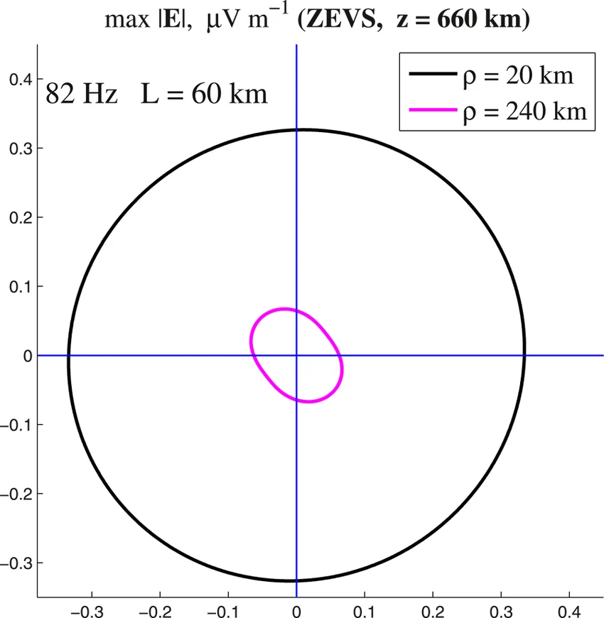
1. Decoding the 82 Hz Upper-Ionosphere Polar Plot (zevs4.png). The scientific plot reproduced above—taken from the peer-reviewed space-physics study by E. N. Fedorov, V. A. Pilipenko, N. G. Mazur, and M. J. Engebretson (2023), "Generation of Artificial ULF/ELF Electromagnetic Emission in the Ionosphere by Horizontal Ground-Based Current System" (Journal of Geophysical Research: Space Physics, 128, e2023JA031590)—models the spatial radiation pattern of ZEVS in the upper nightside ionosphere. Let us unpack every label on the graph:
max |E|, μV m−1 (ZEVS, z = 660 km): The plot shows the horizontal azimuthal distribution (in the x–y horizontal plane, with East–West along the horizontal axis and North–South along the vertical axis, in microvolts per metre) of the major semi-axis of the electric-field polarization ellipse, max |E|, calculated at a fixed orbital altitude of z = 660 km above the Kola Peninsula. Why 660 km? Because 660 km was the orbital altitude of the French CNES microsatellite DEMETER (Detection of Electro-Magnetic Emissions Transmitted from Earthquake Regions, 2004–2010), whose electric and magnetic burst-mode sensors repeatedly detected a sharp 82 Hz spectral line whenever it flew over the Kola Peninsula at night (Pilipenko et al., 2019). The plotted numbers are normalized to a unit antenna current of J0 = 1 A, so to get the real field at ZEVS's operational current of 200 to 300 A, you multiply the axis numbers by 200 to 300. [DOCUMENTED]82 Hz L = 60 km: Earlier theoretical papers (Pilipenko et al., 2019; Fedorov et al., 2020) had simplified ZEVS as an infinitely long 2D current wire (approximated by L = 5,000 km), which predicted a normalized overhead field of ~2.1 to 2.9 μV/m per ampere. In their 2023 paper, Fedorov et al. solved the full 3D Hankel-transform boundary-value problem for ZEVS's realistic finite dipole length of L = 60 km at f = 82 Hz above high-resistivity Kola bedrock (σg = 10-4 S/m). They found that the realistic 60 km finite length reduces the peak field at 660 km altitude by a factor of roughly 6 to 7 compared with an infinite line, down to ~0.325 μV/m per ampere directly above the station. [DOCUMENTED]ρ = 20 km): This curve plots the azimuthal directional diagram of max |E| at 660 km altitude along a circle of horizontal radial offset ρ = 20 km from the vertical axis directly above the midpoint of the ZEVS dipole. The pattern is a large, nearly circular ellipse crossing both axes at approximately ±0.325 μV/m per 1 A. Scaling to a realistic ZEVS current of J0 = 200 A (or 300 A) gives a peak upper-ionospheric electric field at 660 km altitude of ~65 μV/m (up to ~97 μV/m at 300 A) and a transverse magnetic field of ~7 to 10.5 pT! [DOCUMENTED]ρ = 240 km): This curve plots the azimuthal directional diagram at the same 660 km altitude, but at a horizontal radial distance of ρ = 240 km away from the vertical above ZEVS. By ρ = 240 km, the normalized electric field amplitude has decayed to roughly 0.06 to 0.08 μV/m per 1 A (~12 to 24 μV/m at 200–300 A), and the curve forms a slightly tilted ellipse whose maximum (~0.075 μV/m/A) lies near the quadrant diagonals (azimuth φ ≈ 45° / 135°, where |Ex| ≈ |Ey|). The key physical takeaway emphasized by Fedorov et al. is that even though ZEVS on the ground is a linear East–West wire, the 82 Hz emission transmitted upward into the ionosphere is nearly circular (isotropic in azimuth). [DOCUMENTED]2. 2022–2025 Detections by the CSES-01 Satellite and Comparison with the 50 Hz "Severny Tranzit" Grid Line. In 2024 and 2025, V. A. Pilipenko, N. V. Savelyeva, E. N. Fedorov, and Chinese colleagues published new analyses of 2022 overflights of the Kola Peninsula and White Sea by the Chinese-Italian low-Earth-orbiting satellite CSES-01 (China Seismo-Electromagnetic Satellite, orbiting at z ≈ 500 km in a 97.4° sun-synchronous orbit equipped with 4.5-metre electric-field booms and a search-coil magnetometer):
|E| ≈ 1.0 to 3.0 μV/m and |B| ≈ 0.5 to 1.3 pT, matching the 3D finite-dipole model for an active ZEVS antenna current exceeding 100 to 200 A. [DOCUMENTED (Pilipenko et al., 2024, 2025)]|E| ≈ 0.5–2.0 μV/m, |B| ≈ 0.5–1.5 pT) coming from the 330 kV three-phase trunk power line "Severny Tranzit" running south-to-north from Petrozavodsk to Murmansk, where slight phase unbalance over hundreds of kilometres over the resistive Baltic Shield causes the utility grid itself to act as an unintentional ULF/ELF ground dipole! [DOCUMENTED]DUAL-USE GEOPHYSICAL SOUNDING OF THE LITHOSPHERE (ZHAMALETDINOV, VELIKHOV, FENICS)
Because ZEVS can step its thyristor converters and capacitor banks across discrete frequencies from 30 to 200 Hz, it doubles as the most powerful man-made controlled-source electromagnetic (CSEM) deep-crust sounder in Europe. Starting in 1991–1992 under Academician E. P. Velikhov and Dr. A. A. Zhamaletdinov (Geological Institute, Kola Science Centre RAS), Russian and Finnish geophysicists conducted a series of famous experiments across the Baltic Shield:
δcrust = 503.29 √(ρg / f) increases as frequency f decreases, stepping ZEVS from 200 Hz down to 30 Hz (and measuring the ratio of horizontal electric to magnetic fields, the apparent Cagniard magnetotelluric resistivity ρa = (1 / ωμ0) |Ex / Hy|2, at receiving stations 100 to 1,100 km away in Karelia, Finland, and Svalbard) yields a vertical electrical profile of the Earth's crust and upper mantle from 2 km down to 100–200 km depth. [DOCUMENTED]COMPARISON: ZEVS (82 HZ) VS. US NAVY ELF (76 HZ), CHINA (WEM) AND INDIA
Only four countries—the United States, the Soviet Union / Russia, China, and India—have built strategic ELF/SLF submarine communications transmitters. The table below compares ZEVS against its global counterparts [DOCUMENTED]:
| Feature | USSR / Russia: ZEVS («Вариация-1») | USA: Project Sanguine / Seafarer / Naval ELF System | China: WEM (Wireless Electromagnetic Method) | India: Naval ELF Facility |
| Location & Geologic Shield | Kola Peninsula, Murmansk Oblast (68.7° N, 33.7°–35.2° E); Murmansk Block of Baltic Shield | Clam Lake, Wisconsin (NRTF Clam Lake) + Republic, Michigan (NRTF Republic, ~235 km apart); Southern Laurentian Shield | Central China (Huazhong / Dabie–Qinling–Jianghan region, Hubei Province, roughly 5× the area of New York City) | INS Kattabomman (Tirunelveli, Tamil Nadu) / South Indian Peninsular Gneissic Complex |
| Service Dates | 1st module 1983, 2nd module 1985; combat duty 1986 – present (active) | Clam Lake testbed 1969, operational 1982; full dual-site operational 1989 – decommissioned Sept 2004 | Constructed 2011–2018; testing & operational service 2019 – present (active) | Reported operational ~2013–2014 – present |
| Center Frequency & Modulation | 82 Hz (MSK 81.0–83.3 Hz; geophysical 30–200 Hz) | 76 Hz (MSK shifting between 72 Hz and 80 Hz; earlier tests at 45 Hz) | 0.1 Hz to 300 Hz (dual-use submarine ELF + crust/earthquake/resource sounding) | Reported in 3 to 30 / 80 Hz ELF range [SINGLE-SOURCE] |
| Antenna Geometry & Wire Length | Two parallel East–West overhead lines, 60 km each (120 km total), spaced 10 km N–S | Clam Lake (WTF): Two orthogonal 14-mile (22.5 km) lines in an "X" (45 km total). Republic (MTF): One 28-mile (45 km) N–S line + two 14-mile (22.5 km) E–W lines in an "F" (90 km total). Combined total: 135 km (84 miles) |
Two orthogonal grounded overhead lines of ~80 to 120 km each across resistive granite block | Details classified; co-located / associated with INS Kattabomman VLF umbrella complex |
| Antenna Current & Input Power | 200 to 300 A; 2.5 MW per module (5.0 MW total) | 300 A; ~2.6 MW total (~1.0 MW at Clam Lake + ~1.6 MW at Republic) | ~200 to 500 A; ~1,000 kW (1 MW) class | Classified |
| Deep Bedrock Resistivity ρg | 10,000 to 100,000 Ω·m (very high—Archean Murmansk Block granite-gneiss) | ~3,200 to 5,000 Ω·m (moderate-high Laurentian granite/gabbro) | ~5,000 to 10,000 Ω·m | ~5,000 to 10,000 Ω·m |
| Actual Radiated ELF Power | ~2 to 8 watts (measured in 1990 as ~10 dB stronger globally than US 76 Hz system) | ~2.0 to 2.6 watts (both sites phased together) or ~0.5–0.8 W from Clam Lake alone | Estimated ~1 to 5 watts | Unknown |
Why did ZEVS beat the US Navy 76 Hz ELF system by ~10 dB in 1990 global measurements? Looking at the table above, two physical factors explain the 10 dB (10× power / 3.16× field) margin reported in the 1990 Antarctic and ocean measurements (Zhamaletdinov, 2014):
I · L · δcrust along its main lobe is substantially larger. [ESTIMATE]Why the US shut down Clam Lake and Republic in 2004 while Russia kept ZEVS running: In September 2004, the US Navy decommissioned both of its 76 Hz ELF stations, citing annual operating costs (~$12 million/year), the retirement of old single-purpose receivers, and improvements in VLF signal processing and low-profile buoyant fibre/coax mast and towed antennas. Why did the Russian Navy make the opposite decision and keep ZEVS in frontline service? Because of geography and Arctic ice: US Ohio-class SSBNs patrol exclusively in the ice-free open waters of the Pacific and Atlantic Oceans, where trailing a shallow VLF wire at 15–20 metres is always feasible. Russian Northern Fleet Project 667BDRM Delfin and Project 955 Borei SSBNs, by contrast, operate routinely inside the ice-covered Barents, Kara, and central Arctic Ocean bastions, where moving pack-ice pressure ridges make shallow VLF buoys hazardous or unusable for days at a time—making ZEVS's deep-penetrating 82 Hz signal an irreplaceable operational lifeline. [DOCUMENTED / SPECULATION on doctrinal contrast]
SURVIVABILITY, VULNERABILITY AND ROLE IN RUSSIAN NUCLEAR C3
Within the Russian Federation's strategic nuclear command-and-control architecture (covered in Russian C3, Kazbek, and Perimeter), ZEVS forms the deepest-penetrating shore link in a four-tier submarine broadcast chain:
Physical vulnerability of ZEVS in wartime. Like every fixed megawatt VLF or ELF station, ZEVS has an inherent wartime vulnerability paradox:
68.7157° N, 33.7069° E) with its open-air transformer and series-capacitor yard (zevs1.jpg) and the northern transmitter compound (68.8135° N, 33.7538° E, zevs2.jpg) are surface industrial structures at well-known coordinates, and their 120 km of overhead 110 kV lines and external grid feed from Kolenergo cannot be buried underground. In a full-scale nuclear exchange or a coordinated conventional cruise-missile strike that penetrates the Kola air defenses, ZEVS could be knocked off the air early. [ESTIMATE / BACKGROUND]ABOUT THE IMAGES ON THIS PAGE
Consistent with the format of this database, the four images on this page carry no captions beneath them and are documented here:
zevs1.jpg): High-resolution satellite view (Google Maps / Airbus / Maxar Technologies, extracted and supplied by the site owner) of the southern ZEVS main transmitter compound at 68.7156964° N, 33.706883° E (68°42′59″ N, 33°42′28″ E), with the plain text label "Main Transmitter building" added beside the main L-shaped converter hall and the adjacent outdoor step-down substation and series-capacitor tuning yard visible immediately to its north/east. [DOCUMENTED]zevs2.jpg): High-resolution satellite view (Google Maps / Airbus / Maxar Technologies, extracted and supplied by the site owner) of the northern ZEVS station compound at 68.8135068° N, 33.7538109° E (68°48′48″ N, 33°45′06″ E), located ~10.9 km north-northeast of the southern main transmitter building along the north-south access road leading to Severomorsk-3. [DOCUMENTED]zevs3.webp): Topographic map trace (OpenStreetMap / Wikimedia Commons base, supplied by the site owner) showing the two parallel ~60 km east-west horizontal ground-dipole overhead antenna lines and the two western north-south feed corridors in orange across the Kola Peninsula east of Murmansk (Мурманск) and Kola (Кола). [DOCUMENTED]zevs4.png): Scientific polar radiation plot titled max |E|, μV m−1 (ZEVS, z = 660 km) for 82 Hz, L = 60 km at horizontal radial distances ρ = 20 km (black circle) and ρ = 240 km (magenta ellipse), from E. N. Fedorov, V. A. Pilipenko, N. G. Mazur, and M. J. Engebretson (2023), Journal of Geophysical Research: Space Physics, 128, e2023JA031590 (Figure 4), supplied by the site owner. [DOCUMENTED]WHAT IS NOT KNOWN
68.7157° N), but no open document states whether the northern compound relies on indoor capacitor racks or shares high-voltage conditioning with the southern compound.SOURCE CONFLICTS AT A GLANCE
| Point of Conflict | Source Version A | Source Version B | Technical Verdict |
| Total transmitter power (2.5 MW vs. 5.0 MW) | "Up to 2.5 MW" (most RAS geophysical & satellite papers: Velikhov et al., 1994; Pilipenko et al., 2019, 2024) | "Two modules of 2,500 kW each, total 5,000 kW (5 MW)" (ОАО «РИМР» official history of «Вариация-1»; Vasilega) | Both are correct: Each of the two modules is rated at 2.5 MW (and normally only one module/antenna is run at a time, giving 2.5 MW), while running both modules in phase gives 5.0 MW total installed power. |
| Power of ZEVS vs. 200 kW «Синус» / «Энергия» | 2.5 MW per module, 200–300 A (ZEVS / «Вариация-1») | 200 kW, up to 1,000 V, 30–250 A (FENICS mobile generator on 100–120 km industrial power lines) | Different transmitters: The 200 kW generator is a civilian scientific unit used for FENICS soundings on decommissioned/industrial grid lines, not the naval ZEVS transmitter. |
| North-south spacing between the two 60 km lines | 10 km (~10.9 km between transmitter compounds) in Zhamaletdinov (2014), Pilipenko et al. (2025), and satellite imagery | "1 km" in one 2024 conference abstract (doi:10.51981/2588-0039.2024.47.019) | 10 km is proven by satellite imagery and coordinates (68°48′48″ N vs. 68°42′59″ N = 5′49″ of latitude = 10.8 km). "1 km" is a missing-zero typo. |
| Dipole length (55–57 km vs. 60 km) | "About 60 km" in all Russian papers | Great-circle straight distance between published end coordinates is ~56.5 km (northern line) and ~61.2 km (southern line) | Consistent: Because the overhead lines follow terrain contours with slight bends (see zevs3.webp), actual conductor length along each corridor is ~60 km. |
| Upper-ionosphere E-field above ZEVS at 660 km (1 A normalized) | ~2.1 to 2.9 μV/m per A (infinite-line 2D model, Pilipenko et al., 2019; Fedorov et al., 2020) | ~0.32 to 0.5 μV/m per A (realistic 3D finite L = 60 km model, Fedorov et al., 2023, shown in zevs4.png) |
Resolved by Fedorov et al. (2023): The infinite-line approximation overestimated the overhead topside field by a factor of ~6–7; the 60 km finite model (~60–65 μV/m at 200 A) matches DEMETER and CSES-01 observations. |
SUGGESTED SUB-ARTICLES (DATABASE GAPS)
The following related systems touched upon in this reference merit dedicated pages of their own in the Project Orlan database:
RELATED ARTICLES
SOURCES
geo.ksc.ru/images/stories/Print/snch_2014.pdf). Primary source for the development consortium (Navy Long-Range Communications Directorate, NPO im. Kominterna / RIMR, NIIPT, IZK & NIIF LSU, NIRFI), the 82 Hz carrier, 200–300 A current, 2.5 MW module rating, two 60 km antennas, Murmansk Block siting, 1 km2 steel grounding grids, dual-use Kotelnikov/Velikhov program, and the 10 dB global advantage over the 76 Hz US ELF system.doi:10.1029/2023JA031590; preprint doi:10.1002/essoar.10512117.1). Source of the 4th image on this page (zevs4.png, Figure 4) and the finite-dipole (L = 60 km) vs. infinite-line (L = 5,000 km) upper-ionospheric field calculations at z = 660 km (DEMETER altitude) for ρ = 20 km and ρ = 240 km.doi:10.1029/2019JA026929). Documents DEMETER 660 km burst-mode detections of 82 Hz emission above the Kola Peninsula and the 81.0–83.3 Hz frequency-modulation band.doi:10.1016/j.asr.2024.09.041); and Russian companion papers: "Электромагнитное излучение передатчика ЗЕВС и ЛЭП «Северный транзит», зарегистрированное на спутнике CSES", Izvestiya RAN. Seriya Fizicheskaya / Bulletin of the Russian Academy of Sciences: Physics, 2025 (doi:10.31857/S0367676525050096 / doi:10.1134/S106287382571102X), and Dinamicheskie protsessy v geosferakh, Vol. 17, No. 1, 2025 (doi:10.26006/29490995_2025_17_1_35). Documents 2022 CSES-01 detections at 500 km altitude out to 2,300 km, Murmansk Block conductivity down to σg ~ 10-5 S/m, and 50 Hz emissions from the 330 kV "Severny Tranzit" line.computer-museum.ru/connect/rimr.htm), and A. Vasilega, Античные герои на службе Российского флота: primary industrial sources for the 1975–1986 development of the «Вариация-1» ELF complex (2 × 2,500 kW = 5,000 kW, 110 kV-class 60 km lines, 1st module 1983, 2nd module 1985, acceptance into naval service 1986).autoreview.ru/articles/ekspedicii/zevs); and Soumarsov / TsNII «Elektropribor» catalogue records (soumarsov.eu/armes/armes_K.htm): details of the К-657 «Параван» biplane towed antenna (orthogonal magnetic loops, 50–60 m depth, 6 knots) and the К-686 / К-687 «Ласточка» 500 m towed ELF/VLF/HF/UHF submarine receiving systems.vlf.it/zevs/zevs.htm (archived): spectrograms of 82.0 Hz idle carrier and 81.6 / 82.7 Hz MSK transmissions recorded in Cumiana, Italy in 2000, and early-1990s slow Morse tests.IN ONE SENTENCE
ZEVS («ЗЕВС», built around the 2 × 2.5 MW «Вариация-1» solid-state thyristor transmitting complex just south of Severomorsk-3 on the Kola Peninsula and on combat duty since 1986) is the Russian Navy's 82 Hz extremely-low-frequency submarine broadcast station, which pumps 200 to 300 amperes of series-capacitor-tuned alternating current through two parallel 60 km 110 kV-class overhead lines into 1 km2 buried grounding grids atop the ultra-resistive Archean granite of the Murmansk Block, forcing the return current 5 to 18 kilometres deep into the Earth's crust to form a continental-scale vertical magnetic loop that radiates a couple of watts of 82 Hz energy into the global Earth-ionosphere waveguide—enough to penetrate 100 to 400 metres of seawater and Arctic pack ice anywhere on Earth to deliver slow, 5-to-15-minute three-letter bell-ringer and operational action codes to submerged strategic submarines.